


Views: 0 Author: Site Editor Publish Time: 2026-08-27 Origin: Site


Modern electrical infrastructure relies entirely on precise voltage stepping to function safely and efficiently. Without this capability, long-distance power transmission becomes impossible, and equipment safety collapses under unmanageable current levels. Specifying the wrong equipment for your facility introduces severe operational risks. You might face excessive core losses, rapid thermal degradation, or catastrophic facility downtime during peak demand. Field engineers know that matching MVA ratings and impedance levels to specific load profiles prevents these failures. Comparing specific environmental constraints, evaluating thermal management systems, and defining exact specifications ensures safe installation. Proper evaluation guarantees reliable long-term deployment across demanding electrical networks. Whether you manage a rural grid or a heavy manufacturing plant, getting the engineering specifications right on day one dictates the reliability of your entire power system for the next thirty years.
Primary Function: Power transformers are engineered to step-up voltage for efficient long-distance transmission and step-down voltage for safe, localized industrial or commercial distribution without altering frequency.
Application-Specific Sizing: Selecting the correct unit requires matching MVA ratings and impedance levels to the specific load profile, whether for continuous grid operation or fluctuating industrial demand.
Environmental Matching: Deployment location dictates design—liquid-filled units dominate outdoor and rural grids, while dry-type units are mandatory for strict indoor fire safety compliance.
Lifecycle Evaluation: Initial capital expenditure must be weighed against operational efficiency (core/copper losses), cooling requirements, and long-term maintenance demands.
A power transformer transfers electrical energy between independent circuits using concentrated magnetic fields. This process relies entirely on an Alternating Current (AC) supply. A continuously changing magnetic field must exist to induce voltage across the secondary coils based on Faraday's Law of Induction. Direct current cannot achieve this dynamic magnetic flux, making AC mandatory for the system. The equipment establishes a strict inverse relationship between voltage and current. As the unit steps up voltage, it proportionally decreases the current flowing through the conductors. This exact mechanism minimizes copper losses during long-distance transmission. Lower current means significantly less heat generation in the transmission lines. Engineers can move vast amounts of energy efficiently across the grid without melting the overhead conductors. The core utilizes laminated steel sheets to minimize eddy currents and hysteresis losses during this continuous magnetic reversal. Field technicians know that maintaining core integrity prevents excessive heat buildup and extends the operational life of the unit. We rely on precise core stacking techniques during manufacturing to keep these magnetic losses as low as possible. Engineers carefully calculate the magnetic flux density to prevent core saturation during overvoltage events. Saturation causes a massive spike in excitation current, which can trip protective relays and take the unit offline.
These units provide critical galvanic isolation between primary and secondary electrical circuits. There is no direct physical or conductive connection between the input and output wiring. Energy transfers purely through the magnetic core linking the separate windings. Isolating different parts of a power system protects sensitive downstream equipment from upstream disturbances. It blocks destructive fault currents from cascading unchecked through the network. The physical separation mitigates severe voltage spikes caused by lightning or switching surges. It also eliminates ground loops that disrupt sensitive control systems and communication networks. Many units incorporate electrostatic shields between the primary and secondary windings to further attenuate high-frequency common-mode noise. This comprehensive isolation ensures overall grid stability and protects personnel during severe transient fault conditions. Plant operators depend on this isolation to keep variable frequency drives and programmable logic controllers running smoothly even when the incoming utility feed experiences severe voltage sags or harmonic distortion. Grounding the secondary neutral point establishes a stable reference voltage for the entire downstream facility. This prevents floating voltages that can damage sensitive electronics.
Generation facilities produce electricity at relatively low voltages, typically ranging from 11kV to 25kV. Moving this massive energy across vast geographical distances requires stepping the voltage up significantly. Transmission networks elevate this generation voltage to 400kV, 500kV, or even higher. This high-voltage transmission enables safe and highly efficient energy transfer. It minimizes resistive line losses over hundreds of miles of overhead conductors. These massive step-up units interconnect regional grids seamlessly. They allow electricity distribution networks to span cities, states, and entire nations with minimal energy degradation. Grid-level transmission involves continuous, near-maximum load operation. The equipment must withstand constant thermal stress and high dielectric strain without interruption. Engineers design these units with robust insulation systems and advanced cooling mechanisms to survive decades of continuous grid duty. Utility companies monitor these transmission assets constantly, using remote sensors to track oil temperature and dissolved gas levels in real-time. Substation designers utilize specialized surge arresters alongside these units to clamp transient overvoltages before they reach the transformer bushings.
Heavy manufacturing environments demand exceptionally robust electrical infrastructure to maintain production. Steel mills, chemical processing plants, and mining operations present unique and punishing power challenges. These facilities generate severe load fluctuations and high harmonic distortion continuously. Arc furnaces, welding arrays, and large motor starting sequences draw massive inrush currents. Standard commercial distribution equipment cannot survive these punishing electrical conditions. You must deploy a specialized Industrial Power Transformer to manage these extreme operational stresses safely. They feature reinforced core clamping and heavy-duty winding bracing. This internal reinforcement prevents mechanical deformation during frequent short-circuit-like conditions. They also utilize specialized K-factor ratings to handle the excess heat generated by non-linear loads and harmonic frequencies. Plant engineers specify these rugged units to prevent catastrophic failures that could halt an entire production line. The heavy-duty construction ensures the windings do not shift or short out when a massive industrial motor pulls locked-rotor current during startup. Variable frequency drives (VFDs) used in manufacturing create severe harmonic distortion. Engineers must specify electrostatic shields between the primary and secondary windings to block these high-frequency harmonics from polluting the upstream utility grid.
Electricity must eventually transition from high-voltage transmission lines to localized distribution networks. Substations facilitate this critical electrical handoff near densely populated areas. They step down extreme transmission voltages to safe, usable levels for local grids. A typical urban substation reduces 33kV or 66kV down to 11kV or 415V. This lower voltage safely feeds commercial infrastructure, office buildings, and residential neighborhoods. The equipment handles highly variable daily load profiles. Peak demand occurs during business hours or extreme weather events, followed by significant nighttime load drops. The design prioritizes rapid cooling and flexible tap changing capabilities. On-load tap changers (OLTC) automatically adjust the voltage output to compensate for fluctuating grid demand, ensuring consumers receive stable power. Substation technicians perform routine maintenance on these tap changers, filtering the oil and replacing worn contacts to maintain seamless voltage regulation across the city grid. Urban substations often utilize gas-insulated switchgear (GIS) alongside the transformers to minimize the overall footprint in expensive real estate markets.
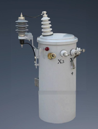
Long-distance distribution networks face variable, lower-density electrical loads spread over vast areas. Equipment deployed in these remote locations endures high exposure to harsh weather conditions. Evaluation criteria must focus heavily on robust weatherproofing and environmental resilience. A high lightning impulse withstand voltage (BIL) is absolutely critical for survival. Lightning strikes frequently target exposed rural overhead lines, sending massive surges toward the equipment. You need a reliable Rural Power Grid Transformer optimized for exceptionally low no-load losses. These units frequently operate well below their peak capacity for extended periods. Minimizing core losses during these low-demand periods ensures long-term operational efficiency. They often feature specialized wildlife guards and heavy-duty protective coatings to resist corrosion in agricultural environments. Linemen rely on these rugged designs to minimize emergency callouts during severe storms. The tank construction must withstand extreme temperature swings without compromising the oil seals or allowing moisture to enter the active part. Pole-mounted units dominate the rural landscape, requiring lightweight designs that do not compromise structural integrity. Single-phase units are common in these applications to serve isolated residential loads.
Commercial buildings, underground facilities, and enclosed industrial plants present severe deployment constraints. Space is limited, and natural ventilation is often poor or entirely absent. Strict fire safety regulations dictate equipment selection in these confined environments. Solutions typically involve cast resin or vacuum pressure impregnated (VPI) dry-type units. Less flammable liquid-filled options utilizing silicone or synthetic ester fluids also exist for specific applications. An Indoor Power Transformer offers superior fire safety compliance and eliminates the need for expensive fire suppression systems. It requires zero fluid maintenance or oil sampling over its lifespan. However, dry-type units have a larger physical footprint per kVA compared to traditional oil-filled designs. They also require clean, filtered ambient air to prevent dust accumulation on the exposed windings. Facility managers must ensure the electrical room has adequate louver sizing and exhaust fans to remove the heat rejected by the dry-type coils. Epoxy cast resin units encapsulate the windings entirely, providing excellent protection against ambient moisture and preventing partial discharge tracking across the coil surfaces.
Industrial environments expose electrical equipment to airborne dust, corrosive chemicals, and continuous mechanical vibration. The electrical loads are equally punishing, highly unpredictable, and often non-linear. Evaluation criteria must prioritize custom impedance ratings during the specification phase. High impedance limits destructive short-circuit currents from damaging sensitive upstream switchgear. Specialized cooling configurations manage the extreme heat generation associated with heavy manufacturing. Robust mechanical bracing is mandatory. It helps the internal windings withstand frequent electrical shocks and thermal cycling. Standard commercial units will fail rapidly under these aggressive industrial conditions. Engineers often specify C5 marine-grade paint finishes to protect the external tank from aggressive chemical vapors. We also see a high demand for specialized bushings that resist heavy particulate buildup in cement plants and mining operations. Mining operations often require skid-mounted units that can be dragged to new locations as the extraction face advances. These mobile substations demand extreme mechanical shock resistance.
Calculating required capacity accurately dictates the success of the entire procurement process. You must analyze the current base load precisely using historical facility data. Factor in projected facility expansion and new equipment integration over the next decade. Redundancy requirements heavily influence the final rating specifications for mission-critical sites. Many data centers and hospitals utilize N+1 configurations to ensure uninterrupted operation during maintenance. Oversizing leads to unnecessary continuous core losses and wasted initial capital. Undersizing causes rapid insulation degradation, thermal overload, and premature asset failure. You must apply accurate demand factors and diversity factors to your specific load profile. Consider specifying a dual-rated unit with forced cooling fans to provide a temporary capacity boost during peak demand emergencies. Electrical designers use load flow studies to verify that the selected MVA rating will maintain acceptable voltage drop limits across the entire facility network. Engineers must also account for the ambient temperature derating factors. A unit rated for 10 MVA at 20°C ambient will not deliver that same capacity safely if installed in a 40°C desert environment without exceeding its temperature rise limits.
Evaluating equipment efficiency requires separating no-load losses from load losses. No-load losses occur continuously in the magnetic core and remain constant whenever the unit is energized. Load losses occur in the copper or aluminum windings and vary squarely with the current demand. You must evaluate manufacturer bids using strict capitalization formulas. The A and B factors determine the true lifecycle energy efficiency impact. The A factor capitalizes the continuous no-load losses over the projected lifespan. The B factor capitalizes the variable load losses based on your anticipated load profile. Balancing these factors ensures you select the most efficient unit. High-efficiency designs utilize premium grain-oriented electrical steel or amorphous metal cores to drastically reduce continuous energy waste. Procurement teams must demand certified test reports to verify that the factory loss measurements match the guaranteed values submitted during the bidding phase. The capitalization rates for A and B factors vary wildly depending on local utility rates and the expected lifespan of the facility. A higher upfront cost for an amorphous core unit often pays for itself within the first five years of operation.
Thermal management directly dictates overload capacity, operational safety, and insulation lifespan. You must compare different cooling classes based on your site conditions and load profile. ONAN (Oil Natural Air Natural) relies entirely on passive fluid convection and ambient airflow. ONAF (Oil Natural Air Forced) adds external radiator fans to increase heat dissipation. OFAF (Oil Forced Air Forced) utilizes internal pumps and external fans for maximum cooling efficiency. Cooling choices impact maintenance schedules, ambient noise levels, and footprint requirements. Forced cooling provides higher peak capacity but introduces mechanical failure points requiring regular inspection.
Cooling Class | Mechanism | Typical Application | Maintenance Need |
|---|---|---|---|
ONAN | Passive oil convection and natural airflow | Rural distribution, low-load substations | Very Low |
ONAF | Passive oil convection with forced fan airflow | Commercial substations, moderate industrial | Medium (Fan checks) |
OFAF | Forced oil pumping and forced fan airflow | Heavy industrial, high-voltage transmission | High (Pump/Fan checks) |
ODWF | Directed oil flow with water heat exchangers | Extreme space constraints, underground facilities | Very High |
Inadequate site preparation introduces severe operational, structural, and environmental risks. Poor foundation design leads to uneven settling, which stresses internal connections and external piping. Oil containment failures violate strict environmental spill prevention laws and incur massive penalties. Acoustic noise limits often dictate placement parameters in dense urban environments. You must conduct thorough site surveys before finalizing equipment specifications. Mandate strict adherence to local environmental codes and zoning regulations. Design robust secondary containment systems, such as concrete catch basins, for all liquid-filled units. Ensure adequate physical clearance for heavy maintenance access, crane positioning, and optimal radiator airflow. Install vibration isolation pads to prevent low-frequency hum from transferring into adjacent building structures. Civil engineers must verify the soil bearing capacity before pouring the concrete pad to prevent long-term subsidence issues. Fire walls or blast partitions are often required between adjacent units to prevent a catastrophic failure in one transformer from destroying the neighboring equipment.
Operational risks compound rapidly over time without rigorous lifecycle management. Insulation degradation and moisture ingress threaten internal dielectric strength continuously. Oil contamination accelerates paper insulation breakdown and causes rapid, catastrophic failure. You must implement routine dissolved gas analysis (DGA) protocols. DGA detects trace gases like hydrogen and methane that indicate specific internal faults, arcing, or localized overheating. Schedule regular thermography scans to identify external connection hotspots before they melt. Perform scheduled dielectric testing, including power factor and sweep frequency response analysis (SFRA), to verify insulation integrity. Check silica gel breathers regularly to ensure moisture stays out of the conservator tank. Proactive maintenance extends the asset lifespan by decades and prevents unplanned facility outages. Maintenance crews should also perform regular visual inspections of the bushings to check for oil leaks or porcelain cracks. Sweep frequency response analysis (SFRA) acts as a mechanical fingerprint for the active part. Comparing baseline SFRA traces against future tests reveals if the windings have shifted or deformed after a severe short circuit.
Procurement specifications must align strictly with recognized international engineering standards. Ensure complete compliance with IEEE, IEC, ANSI, and NEMA guidelines based on your region. These standards dictate rigorous testing protocols, safety margins, and performance baselines. Factory acceptance testing (FAT) is a mandatory step prior to shipment authorization. FAT verifies all performance guarantees under controlled laboratory conditions. It confirms impedance values, loss measurements, temperature rise limits, and dielectric withstand capabilities. Never accept delivery without a comprehensive, documented FAT report signed by the lead testing engineer. Require short-circuit withstand testing documentation for units destined for heavy industrial applications. Compliance ensures the equipment will perform safely under both normal and fault conditions. Third-party inspectors often witness these factory tests to provide an unbiased verification of the manufacturer's claims. Temperature rise tests during the FAT involve running the unit at full load until the oil and winding temperatures stabilize. This proves the cooling system can handle the continuous thermal output without degrading the paper insulation.
Define your exact load requirements, including precise MVA ratings, harmonic profiles, and required impedance levels based on historical facility data.
Select the appropriate dielectric and cooling medium based on indoor fire codes, outdoor weather exposure, or industrial contamination risks.
Evaluate the lifecycle energy efficiency by applying capitalization factors to balance continuous core losses against variable copper losses.
Finalize your single-line diagrams and site layouts with a specialized electrical engineer to verify clearances and containment.
Request detailed technical proposals, cooling performance data, and comprehensive FAT documentation from certified manufacturers.
A: Power transformers operate near full load continuously in high-voltage transmission networks to move massive amounts of energy over long distances. Distribution transformers handle fluctuating, lower-voltage loads at the consumer end, stepping power down for residential or commercial use.
A: No. Transformers require an Alternating Current (AC) supply to create the continuously fluctuating magnetic field necessary for electromagnetic induction. They cannot step up or step down DC voltage because a static magnetic field induces no current.
A: These units typically boast a 25 to 40-year lifespan. This longevity is heavily contingent on rigorous maintenance, strict load management, proactive oil testing, and keeping operating temperatures within specified design limits.
A: Dry-type units comply with strict indoor fire safety codes. They eliminate the risk of flammable oil spills, remove the need for expensive concrete containment infrastructure, and do not require complex fire suppression systems.
A: The primary causes include internal insulation breakdown, severe lightning strikes, sustained thermal overloading, and poor maintenance. Neglecting oil maintenance often leads to moisture ingress, which rapidly degrades the dielectric strength.
A: Sizing requires calculating the peak demand of the rural network while factoring in future load growth. Engineers prioritize units with exceptionally low core losses because rural grids frequently experience extended periods of low demand.
A: Modern units typically exceed 98% to 99% efficiency. Even fractional percentage improvements in efficiency yield massive energy savings over the asset's lifespan, making low-loss core designs highly valuable.

