


Views: 0 Author: Site Editor Publish Time: 2026-08-09 Origin: Site


Localized voltage regulation forms the backbone of modern electrical distribution networks. Grid reliability hinges entirely on precise equipment specification. Misaligning these specifications with actual load profiles introduces severe operational risks to the infrastructure. Field engineers often face excessive core losses, rapid thermal degradation, and premature equipment failure when they ignore fundamental operational mechanics. Overlooking these mechanics compromises network stability. A deep understanding of underlying electromagnetic principles serves as a mandatory framework for engineers and procurement teams. We use this knowledge to evaluate efficiency, specify materials, and select the correct form factor for targeted grid deployments. When you deploy equipment without analyzing specific environmental constraints, you risk catastrophic failure during peak demand. The physics of electromagnetic induction dictate how well a unit handles transient overvoltages and continuous load cycling. By mastering these principles, you can accurately match impedance values, optimize cooling mechanisms, and prevent costly outages. This guide breaks down the technical specifications required to build a resilient distribution network.
Operational Foundation: As a static device with no moving parts, every single phase transformer relies on Faraday’s Law of Electromagnetic Induction; understanding mutual inductance and magnetizing current is critical for evaluating voltage regulation capabilities under varying loads.
Material Impact on Efficiency: The choice between core-type and shell-type construction, as well as winding materials (copper vs. aluminum), directly dictates the unit's thermal performance and total lifecycle cost.
Application Specificity: Deployment environments dictate design; a pole mounted single phase transformer requires different structural and environmental specifications compared to pad-mounted or indoor units.
Procurement Metrics: Technical evaluation must prioritize impedance matching, load-loss ratios, EMF design formulas, and adherence to IEEE/IEC standards over baseline capital expenditure.
We define the single phase transformer as a highly efficient static electrical device. It transfers electrical energy between two or more circuits through electromagnetic induction. It accomplishes this energy transfer without changing the system frequency. Alternating current enters the primary winding from the source network. This action draws a specific magnetizing current into the system. The current generates an alternating magnetic flux within the steel core. This alternating flux then links to the secondary winding across the core. The magnetic linkage induces an electromotive force within the secondary circuit.
The efficiency of this flux linkage connects directly to manufacturer material quality. High-grade cold-rolled grain-oriented silicon steel minimizes internal magnetic resistance. This material selection directly dictates the resulting no-load iron losses. Engineers must evaluate the magnetic permeability of the core material during specification. Poor core materials require higher magnetizing currents to establish the necessary flux. This inefficiency leads to continuous energy waste regardless of the connected load. Procurement teams must scrutinize material certifications to ensure long-term operational efficiency. We look for specific core loss guarantees in watts per kilogram at standard operating flux densities.
The turns ratio determines the specific voltage step-up or step-down functions. You calculate this ratio by dividing primary winding turns by secondary turns. An inverse relationship exists between voltage and current during this transformation process. This mathematical relationship maintains power equivalence across the entire device. When voltage increases on the secondary side, the available current decreases proportionally. This principle allows high-voltage transmission lines to interface with low-voltage distribution networks safely.
Engineers must calculate required secondary voltage stability under peak load conditions. This calculation helps specify the correct turns ratio for the deployment zone. It also dictates necessary tap changer requirements for the local network. Standard distribution units often feature a five-position de-energized tap changer. These tap changers allow manual adjustments to the turns ratio in 2.5 percent increments. These adjustments compensate for upstream voltage fluctuations from the primary grid. Proper impedance matching ensures the secondary voltage remains within acceptable regulatory limits. You must account for maximum anticipated load currents when designing these parameters.
The universal EMF equation provides the mathematical foundation for all transformer design. The formula relies on system frequency, total number of turns, and maximum magnetic flux. These variables interact to dictate the physical size of the unit. They also establish the absolute efficiency limits of the magnetic circuit. A higher system frequency allows for a physically smaller core cross-section. Conversely, lower frequencies demand larger, heavier cores to prevent magnetic saturation.
Procurement teams must equip themselves to question manufacturers on flux density optimization. Proper optimization prevents core saturation during unexpected grid voltage spikes. Most modern designs target a nominal operating flux density between 1.5 and 1.7 Tesla. When a core saturates, it can no longer contain additional magnetic flux. This condition causes a massive spike in primary current draw. The resulting thermal stress can quickly degrade internal paper insulation. You must verify that the designed maximum flux density leaves adequate headroom. This engineering margin protects the equipment during transient overvoltage events.
Three primary static components make up the internal architecture of the device. These include the magnetic steel core, the primary winding, and the secondary winding. Manufacturers utilize two main magnetic core configurations for distribution applications. Core-type designs feature copper or aluminum windings that surround the core limbs. Shell-type designs feature a central core that surrounds the internal windings. Each configuration offers distinct mechanical and electrical advantages for specific deployment scenarios.
Core-type units offer easier maintenance access and simplified insulation wrapping processes. They dissipate heat effectively because the windings remain exposed to the cooling medium. Shell-type units provide superior mechanical protection for the internal coil structures. They also demonstrate lower leakage reactance due to tighter magnetic coupling. You must evaluate these structural trade-offs against your specific operational requirements. Heavy industrial applications often favor shell-type designs for their robust short-circuit withstand capabilities.
Feature | Core-Type Construction | Shell-Type Construction |
|---|---|---|
Winding Placement | Windings surround the core limbs | Core surrounds the internal windings |
Maintenance Access | Easier to inspect and repair in the field | More difficult to disassemble without factory tools |
Leakage Reactance | Relatively higher due to winding separation | Significantly lower due to tight magnetic coupling |
Mechanical Strength | Standard structural support for normal loads | High resistance to extreme short-circuit forces |
Cooling Efficiency | Excellent winding heat dissipation | Requires careful cooling duct design to prevent hot spots |
Copper and aluminum serve as the primary winding materials in modern manufacturing. Copper offers higher electrical conductivity and a smaller physical footprint. Aluminum provides a much lighter weight alternative for overhead installations. Thermal expansion rates differ significantly between these two conductive metals. Aluminum expands more than copper under heavy thermal load conditions. Manufacturers must design internal bracing systems to accommodate this physical expansion. Failure to secure the windings leads to mechanical abrasion of the insulation.
Insulation classes determine the maximum allowable operating temperatures for the unit. Standard kraft paper provides baseline dielectric strength for oil-filled applications. Thermally upgraded paper allows for higher operating temperatures without accelerated aging. Dielectric strength requirements depend heavily on expected load cycling and environmental conditions. You must specify insulation classes that exceed your maximum anticipated ambient temperatures. This proactive specification prevents premature breakdown of the internal dielectric barriers. We typically specify Class 120 or Class 155 insulation systems for standard distribution environments.
Cooling methods split into dry-type and liquid-filled operational categories. Dry-type units rely entirely on ambient air circulation for heat dissipation. Liquid-filled units utilize highly refined mineral oil or synthetic ester fluids. The fluid acts as both a cooling medium and a dielectric insulator. As the core heats up, the fluid circulates through natural convection. This circulation pulls heat away from the active components toward the outer tank. Radiator fins increase the external surface area to accelerate this heat transfer process.
The cooling choice impacts environmental compliance and fire risk mitigation strategies. Mineral oil presents a flammability risk and requires secondary containment systems. Synthetic esters offer higher flash points and rapid environmental biodegradability. Dry-type units eliminate fluid leak risks entirely but require larger physical footprints. Maintenance schedules also vary drastically based on the selected cooling medium. You must align the cooling mechanism with your specific site safety requirements. Indoor installations almost exclusively mandate dry-type or less-flammable liquid configurations.
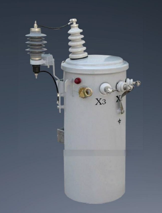
Overhead distribution networks demand highly specific structural requirements for equipment. Weight limitations dictate the maximum allowable size of the deployed unit. Utility poles can only support a specific mechanical load before structural failure. Secure mounting brackets ensure stability during severe weather events and high winds. Weatherproofing protects internal components from moisture ingress and ultraviolet degradation. The outer tank must feature corrosion-resistant coatings to survive decades of exposure. We specify heavy-duty NEMA standard mounting lugs for all overhead deployments.
A standard pole mounted single phase transformer typically ranges from 5 kVA to 167 kVA. These specific capacities perfectly suit residential and light commercial overhead drops. Smaller units serve individual remote households or small agricultural pumping stations. Larger units handle high-density residential streets or small commercial strip malls. You must match the kVA rating strictly to the calculated downstream load profile. Oversizing wastes capital, while undersizing leads to rapid thermal failure. Field engineers must also account for future load growth when selecting the final kVA rating.
Long-distance distribution lines present unique engineering challenges for grid operators. Low-density population areas often utilize Single Wire Earth Return (SWER) systems. A rural single phase transformer must endure harsh, isolated environmental exposures. These units operate far from immediate maintenance access or rapid repair crews. Robust surge protection becomes absolutely critical in these highly exposed deployments. Lightning strikes pose a constant threat to overhead lines in open terrain.
High Basic Impulse Level (BIL) ratings help withstand these severe lightning strikes. The BIL rating indicates the maximum voltage transient the insulation can survive. Rural units often require higher BIL ratings than their urban counterparts. We frequently specify 95 kV or 125 kV BIL ratings for exposed 15 kV class networks. They also protect against severe grid anomalies caused by falling trees or wildlife. You must specify heavy-duty wildlife guards for all exposed primary bushings. This simple addition prevents widespread outages caused by phase-to-ground animal contacts.
Individual units must coordinate directly within the broader grid architecture. This coordination balances electrical loads across the entire distribution network. It also minimizes line losses over extended rural transmission distances. A well-integrated rural power grid transformer ensures stable power delivery to remote end-users. Engineers must carefully map out the placement of each unit along the feeder. Strategic placement maintains acceptable voltage levels at the very end of the line.
You must match transformer impedance with specific grid characteristics. This matching prevents unacceptable voltage drops at the end of long rural feeders. High impedance units limit short-circuit currents but cause larger voltage drops under load. Low impedance units maintain better voltage stability but allow higher fault currents. You must calculate the perfect balance based on your specific conductor sizing. Proper integration requires comprehensive load flow studies before physical deployment begins. We utilize specialized software to model these voltage drops across miles of overhead conductor.
Managing energy losses remains a top priority for modern grid operators. No-load losses occur continuously due to hysteresis and eddy currents within the core. These losses happen 24 hours a day, regardless of customer power consumption. Load losses fluctuate dynamically based on winding resistance and actual current flow. As customer demand increases, load losses rise exponentially due to internal heating. The combination of these two factors determines the total operational efficiency.
You must evaluate manufacturer test reports carefully during the procurement phase. Focus heavily on peak efficiency load points and loss optimization formulas. Some designs optimize for low no-load losses at the expense of higher load losses. Other designs balance the two for highly variable residential load profiles. You must demand certified test data proving the guaranteed loss values. Penalize manufacturers heavily during the bidding process if they fail to meet these guarantees.
Request the certified factory test report detailing exact no-load and load loss measurements.
Compare the tested loss values against the guaranteed maximums specified in the original purchase order.
Calculate the actual efficiency at 50 percent and 100 percent load conditions.
Verify the temperature rise data remains within the specified insulation class limits.
Percentage voltage regulation indicates the actual power quality delivered to the end-user. You calculate this metric from no-load states up to full-load operational states. Lower percentage values indicate superior voltage stability under heavy demand. High regulation percentages result in dimming lights and damaged customer electronics. You must specify strict regulation limits based on local utility commission requirements. The internal winding design directly dictates this critical performance metric.
Percentage impedance determines the maximum short-circuit current capacity of the unit. It also dictates the viability of parallel operation with other deployed units. Transformers operating in parallel must possess nearly identical impedance values. Mismatched impedance causes circulating currents that overheat the internal windings. You must verify the impedance tolerance limits during the factory inspection phase. A standard tolerance of plus or minus 7.5 percent is typical for distribution units. We reject any unit that falls outside this strict impedance tolerance window.
Factory Acceptance Testing validates the entire design and manufacturing process. Routine tests check basic winding resistance, voltage ratio, and magnetic polarity. These tests ensure the unit matches the baseline engineering specifications. Type tests verify temperature rise limits and impulse withstand capabilities. Manufacturers perform type tests on a single unit to validate a new design family. Special tests address specific environmental requirements like extreme cold weather performance.
Documented compliance with regional standards remains mandatory before procurement sign-off. You must require strict adherence to IEEE C57.12.20 or IEC 60076 standards. Review all certified test reports before allowing the units to ship. Check the dissolved gas analysis results of the oil after the temperature rise test. Any presence of combustible gases indicates internal sparking or localized overheating. Never accept a unit that fails to pass all mandatory FAT protocols.
Test Category | Specific Test Performed | Primary Purpose |
|---|---|---|
Routine Test | Winding Resistance Measurement | Verifies manufacturing consistency and detects internal connection faults. |
Routine Test | Voltage Ratio and Polarity | Ensures the turns ratio matches the nameplate and phase relationships are correct. |
Type Test | Temperature Rise Test | Confirms the cooling system maintains temperatures within the specified insulation class. |
Type Test | Lightning Impulse Test | Validates the BIL rating and insulation strength against transient overvoltages. |
Special Test | Short-Circuit Withstand | Proves the mechanical integrity of the core and windings under severe fault conditions. |
Installation failures often stem from basic procedural oversights in the field. Improper grounding creates severe safety hazards for line technicians and the public. A poor ground connection prevents internal surge arresters from functioning correctly. Incorrect tap settings lead to immediate voltage regulation issues for connected customers. Field crews must verify the primary voltage before setting the final tap position. Mishandling during pole hoisting can severely damage internal core structures and insulation.
Mitigation strategies require mandatory certified contractor usage for all installations. Implement strict pre-energization checklists to ensure all connections meet engineering tolerances. Inspect all external bushings for hairline cracks caused by transport vibration. Verify the oil level indicator shows the correct fluid volume before applying power. Test the secondary voltage at the meter base before connecting the customer load. These simple steps prevent catastrophic failures during the initial energization phase.
Perform a visual inspection of the outer tank and bushings for physical damage.
Verify the nameplate voltage matches the actual primary line voltage.
Confirm the tap changer is locked into the correct position for the local grid conditions.
Measure the ground resistance to ensure it falls below utility maximum thresholds.
Conduct a final insulation resistance test using a megohmmeter before applying primary power.
Long-term maintenance requirements dictate the true operational lifespan of the unit. Oil-filled transformers require periodic dissolved gas analysis to monitor internal health. This analysis detects internal faults long before catastrophic failure occurs. Routine visual inspections check for tank corrosion, fluid leaks, and bushing degradation. You must maintain clear vegetation clearances around pole-mounted units to prevent fire hazards. Proper maintenance scheduling maximizes the longevity of the deployed asset.
Dry-type units demand frequent visual inspections to ensure clear ventilation pathways. Dust accumulation on the internal coils severely degrades their cooling capacity. Environmental trade-offs exist between fluid containment risks and physical footprint requirements. Oil spills require immediate environmental remediation and soil testing. Dry-type units avoid this risk but remain highly susceptible to moisture ingress. You must weigh these physical maintenance realities against your available field resources. We recommend establishing a strict five-year maintenance cycle for all distribution assets.
The fundamental working principle of electromagnetic induction dictates every aspect of a transformer's efficiency, physical size, and operational lifespan. You cannot separate the underlying physics from the practical realities of grid deployment. Procurement and engineering teams must base their shortlists on a strict alignment of load profiling and environmental constraints. Verifiable loss metrics and impedance matching must take precedence over basic capital expenditure. A poorly specified unit will drain resources through continuous energy losses and premature failure.
Take the following actions to ensure successful deployment:
Audit your current grid load data to identify peak demand periods and baseline usage.
Define specific environmental requirements, including BIL ratings and cooling mechanisms, for your targeted deployment zones.
Request comprehensive technical datasheets and guaranteed loss metrics from all shortlisted manufacturers.
Verify all Factory Acceptance Testing documentation thoroughly before granting final shipping approval.
A: It operates on Faraday's Law of Electromagnetic Induction. Alternating current in the primary winding creates a magnetizing current. This generates an alternating magnetic flux in the core. The flux links to the secondary winding, transferring electrical energy between circuits through mutual inductance without changing the frequency.
A: It contains no moving or rotating mechanical parts. The entire energy transfer process relies purely on alternating magnetic fields within the stationary steel core. This lack of movement minimizes mechanical wear and tear, resulting in high operational efficiency and a long service life.
A: Pole-mounted units feature specific weight constraints, specialized mounting brackets, and weatherproofing for overhead distribution. Pad-mounted units are heavier, sit on concrete foundations, feature secure ground-level enclosures, and connect primarily to underground distribution networks.
A: They provide a highly cost-efficient method for running extended power lines over long distances. In low-density population areas, installing single-phase infrastructure requires less wire and fewer poles compared to heavy three-phase systems, making it ideal for remote deployments.
A: Energy losses stem from two main sources. Core or iron losses occur continuously due to magnetic hysteresis and eddy currents within the steel. Copper or load losses fluctuate based on current demand, caused by the natural electrical resistance of the winding materials generating heat.

