


Views: 0 Author: Site Editor Publish Time: 2026-08-11 Origin: Site


Correctly interpreting a wiring diagram stands as the primary barrier between a safe electrical installation and catastrophic equipment failure. Specifying and wiring transformers requires matching exact load requirements with primary and secondary voltage configurations. Miscalculations or wiring errors lead to code violations, efficiency losses, and severe safety hazards like arc flashes or overheating. Engineers and electricians rely on accurate schematics to ensure proper phase alignment and load distribution. A single mistake in jumper placement can instantly destroy a newly installed unit. Field execution relies entirely on understanding how abstract lines on a page map to physical copper terminals. Guesswork during this phase guarantees failure. This guide deconstructs standard wiring diagrams, outlines the technical evaluation criteria for selecting the right unit, and provides a framework for mitigating implementation risks when deploying these transformers in commercial or residential environments.
Terminal Identification is Standardized: Primary connections are universally designated with "H" terminals, while secondary connections use "X" terminals; understanding this polarity is non-negotiable for safe installation.
Application Dictates Configuration: A residential single phase transformer typically requires a split-phase configuration (120/240V), whereas industrial control circuits may require dedicated isolation step-down setups.
Sizing Requires Precision: Selecting a unit based solely on voltage is insufficient; accurate kVA sizing, accounting for continuous and inrush loads, is required to prevent premature failure.
Compliance is Mandatory: Proper grounding, bonding, and overcurrent protection must align with NEC (National Electrical Code) or local jurisdictional standards to mitigate liability and operational risk.
Engineers and contractors must translate schematic symbols into physical connections without ambiguity. You start this process with the manufacturer's provided data. You must systematically decode the nameplate before stripping a single wire or pulling any conduit. The transition from a paper schematic to a physical terminal block requires a strict sequence of verification steps to ensure you do not cross phases or create a dead short.
Locate the physical nameplate permanently affixed to the front or side of the enclosure.
Identify the primary voltage rating and the corresponding H-terminal configuration required for your supply voltage.
Identify the secondary voltage rating and the corresponding X-terminal configuration required for your load.
Verify the impedance percentage (%Z) to calculate the available short-circuit current for downstream breaker sizing.
Check the temperature rise and insulation class to select appropriately rated wire insulation and terminal lugs.
Locate the factory wiring diagram on the physical nameplate. Manufacturers permanently affix this metal or heavy-duty vinyl tag to the exterior enclosure. It serves as the ultimate authority for that specific unit. Never rely on generic diagrams found online when terminating field connections. The nameplate dictates the exact jumper configurations required for your target voltage. If the nameplate is missing or illegible, you cannot legally or safely install the unit.
Interpret critical supplementary data alongside the schematic. Look for the impedance percentage (%Z). This value determines the maximum short-circuit current the unit can deliver. You calculate the short-circuit amps by dividing the full load amps by the decimal value of the impedance. You need this number to properly size the interrupting rating of downstream circuit breakers. Check the insulation class and temperature rise. A 150°C temperature rise indicates the unit runs hot by design. This metric dictates your wiring methods. You must select terminal lugs and wire insulation rated for high temperatures, typically 90°C, to prevent the insulation from melting off the conductors inside the enclosure.
Standard NEMA nomenclature defines terminal markings clearly. High voltage connections always use H designations. You will see terminals labeled H1, H2, H3, and H4. Low voltage connections use X designations, such as X1, X2, X3, and X4. Do not confuse primary with high voltage automatically. A step-up application uses the X terminals as the primary input and the H terminals as the secondary output. Always verify your specific application and supply voltage before landing any wires.
Understand the physical relationship between the coils and the magnetic core. Schematic symbols represent physical isolation. The primary and secondary windings do not touch. Magnetic flux transfers the energy across the laminated steel core. The wiring diagram shows this separation using parallel lines between the coil symbols. This galvanic isolation protects sensitive secondary equipment from primary-side electrical faults. It also means the secondary side establishes a completely new electrical system, requiring its own dedicated grounding infrastructure.
Polarity directly affects parallel operation and phase relationships. When you wire two transformers together to increase capacity, their polarities must match exactly. If you parallel an additive unit with a subtractive unit, you create a dead short across the secondary terminals. This results in immediate breaker tripping, massive arcing, and potential winding destruction. Polarity dictates the relative direction of induced voltages in the primary and secondary coils at any given millisecond.
Follow the standard industry rule for quick identification. Transformers under 200 kVA and under 8,660V are typically additive. Units exceeding these thresholds are generally subtractive. However, always verify the polarity dot convention on the nameplate diagram. Additive polarity means the H1 and X1 terminals sit diagonally across from each other on the physical terminal block. Subtractive polarity places H1 and X1 directly adjacent to each other. If you cannot read the nameplate, you must perform an AC voltmeter test by jumping H1 to X1, applying a low voltage to the primary, and measuring the voltage across H2 and X2 to determine the polarity.
Series connections suit high-voltage applications. Dual-voltage primary windings allow a single unit to accept two different supply voltages. For a 240/480V primary accepting 480V, you must wire the coils in series. You typically link H2 to H3 using a factory-provided jumper. You then land your incoming line conductors on H1 and H4. This forces the current through both coils sequentially, utilizing the full impedance of the winding to handle the higher voltage.
Parallel connections handle low-voltage, higher-current applications. If that same 240/480V primary receives a 240V supply, you wire the coils in parallel. You link H1 to H3, and you link H2 to H4. You then land your incoming lines on H1 and H4. This divides the current across both coils simultaneously. Proper physical execution is non-negotiable. Use only the manufacturer-provided copper links or heavy-gauge jumpers across the terminal block. Torque all connections to the exact inch-pound specifications listed on the nameplate. Loose jumpers cause high resistance, localized heating, and eventual terminal failure.
Primary Voltage Input | Winding Configuration | Jumper Placement | Line Connections |
|---|---|---|---|
High (e.g., 480V) | Series | Connect H2 to H3 | Lines to H1 and H4 |
Low (e.g., 240V) | Parallel | Connect H1 to H3; H2 to H4 | Lines to H1 and H4 |
Match the wiring method to the specific facility or residential requirement. A generic approach fails in specialized environments. You must align the internal coil configuration with the external load demands. Different applications require distinct secondary wiring strategies to deliver safe, usable power while maintaining code compliance.
Diagram breakdowns reveal how to reduce primary distribution voltage to usable utilization voltage. Industrial facilities often distribute power at 480V to minimize copper costs and reduce voltage drop over long runs. However, standard equipment requires 120V. A single phase step down transformer bridges this gap. The primary diagram shows a series connection for 480V. The secondary diagram shows a parallel connection for a straight 120V output, or a series connection with a center tap for a 120/240V output.
Use cases dictate the exact secondary wiring. Machine tool control circuits require a dedicated 120V supply isolated from the main power grid. You wire the secondary coils in parallel (X1 to X3, X2 to X4) to maximize current capacity at 120V. You then ground one side of this secondary (usually X2/X4) to establish a grounded neutral reference. Commercial lighting circuits may require a 120/240V split-phase setup to balance the lighting load across two legs. Isolated equipment loads benefit from the galvanic isolation, preventing ground loops and electrical noise from interfering with sensitive electronics like PLCs or medical imaging machines.
Utility distribution relies heavily on the center-tapped secondary configuration in North America. Utility poles step down high-voltage distribution lines, often 7200V or 14400V, to feed individual homes. The secondary side utilizes a specific wiring method to provide versatile power. This configuration relies on a center tap to create two distinct voltage levels from a single magnetic core, feeding the standard triplex overhead drop to the residential weatherhead.
A single 240V secondary winding splits to provide two 120V legs and a neutral. A residential single phase transformer achieves this by bonding X2 and X3 together internally or at the external terminal block. This bonded point becomes the neutral center tap. The utility connects this center tap directly to the earth ground at the pole, and the electrician grounds it again at the main service panel. Measuring from X1 (Line 1) to the neutral yields 120V. Measuring from X4 (Line 2) to the neutral yields 120V. Measuring across the outer terminals, X1 to X4, yields the full 240V required for heavy appliances like electric ranges, dryers, and central air conditioners.
Modern homes contain multiple sub-systems requiring distinct voltage levels far below the standard 120V wall outlet. HVAC control boards operate on 24VAC. Low-voltage landscape lighting utilizes 12VAC or 15VAC. Doorbell chimes require 16VAC. EV charging stations sometimes require isolation to prevent DC fault currents from entering the home's AC system. You must size and wire these localized units precisely to prevent burning out delicate control boards.
Compare isolation transformers versus auto-transformers in these environments. A household single phase transformer used for isolation provides two separate windings. This ensures safety by breaking the physical electrical connection between the primary line voltage and the secondary low voltage. Auto-transformers use a single continuous winding for both primary and secondary, tapping off a section of the coil to reduce voltage. They are smaller and cheaper but offer no isolation. Auto-transformers present severe safety risks if the neutral connection fails, as the full primary voltage can suddenly appear on the secondary terminals. Because of this risk, isolation units remain the standard for consumer-facing household applications.
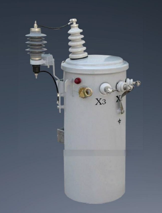
Move beyond the diagram to select hardware based on features-to-outcomes and scalability. Wiring a unit correctly matters little if the unit itself is undersized or poorly suited for the environment. Specification requires rigorous mathematical calculation and environmental assessment. You must evaluate load profiles, voltage fluctuations, and physical installation constraints before ordering the equipment.
Calculate the required capacity using the standard formula for single-phase kVA: (Volts × Amps) / 1000. If you have a 240V load drawing 50 amps, the calculation is (240 × 50) / 1000, which equals 12 kVA. You cannot simply purchase a 12 kVA unit. Running a single phase transformer at 100% capacity continuously causes extreme heat buildup, rapid insulation degradation, and eventual core failure.
Factor in a 20-25% buffer for future capacity and continuous load requirements. For a 12 kVA load, select a standard 15 kVA unit. This buffer ensures longevity and accommodates minor facility expansions without requiring a complete equipment swap. Account for motor inrush currents to prevent nuisance tripping. Motors draw up to six times their running current upon startup. If your load consists primarily of motors, you must size the kVA significantly higher to handle these transient spikes without dropping the secondary voltage and stalling the equipment.
Standard kVA Rating | Full Load Amps at 120V | Full Load Amps at 240V | Full Load Amps at 480V |
|---|---|---|---|
5 kVA | 41.6 A | 20.8 A | 10.4 A |
10 kVA | 83.3 A | 41.6 A | 20.8 A |
15 kVA | 125.0 A | 62.5 A | 31.2 A |
25 kVA | 208.3 A | 104.1 A | 52.0 A |
Utility power rarely arrives at exactly 480V or 240V. Voltage drop across long facility wire runs further reduces the voltage reaching your equipment. Transformers include primary voltage taps to correct these discrepancies. These taps slightly alter the turns ratio between the primary and secondary coils. You will typically see FCAN (Full Capacity Above Normal) and FCBN (Full Capacity Below Normal) taps listed on the nameplate, usually in 2.5% or 5% increments.
Use taps to compensate for consistently high or low utility supply voltage. If your incoming voltage measures 456V instead of the nominal 480V, your secondary voltage will drop proportionally, potentially causing motors to run hot and fail. By moving the primary jumpers to the 5% FCBN tap, you decrease the number of active primary winding turns. This changes the ratio and restores the secondary output to the correct 120/240V level. This regulation protects sensitive downstream equipment from brownouts. Always measure the incoming voltage with a true RMS multimeter under normal load conditions before adjusting the taps.
Evaluate NEMA enclosure ratings based on the installation environment. NEMA 1 enclosures suit clean, dry indoor locations like electrical rooms or commercial hallways. They offer basic protection against falling dirt but fail immediately in damp areas. NEMA 3R enclosures provide outdoor, weather-resistant protection. They feature overlapping panels and weep holes to shed rain, sleet, and snow. NEMA 4X enclosures withstand corrosive environments, utilizing stainless steel or fiberglass to resist harsh chemicals, salt spray, and high-pressure washdowns in industrial food processing plants.
Consider the impact of enclosure choice on cooling and wiring conduit entry points. Ventilated enclosures rely on ambient air circulation to dissipate heat. You must keep their louvers clear of obstructions. Encapsulated units seal the core and coils in a solid block of epoxy resin mixed with silica sand. They dissipate heat directly through the enclosure walls, making them ideal for dusty, damp, or hazardous locations where airborne particulates would destroy a ventilated unit. Always verify that your chosen enclosure allows for proper conduit routing. Punching a hole in the top of a NEMA 3R enclosure instantly voids its weather-resistant rating.
Address the physical, safety, and compliance hurdles during installation. The transition from specification to physical wiring introduces significant risk. Human error, faulty components, or code violations can turn a routine installation into a hazard. Implement strict testing and verification protocols to mitigate these risks before applying primary power.
Conduct continuity checks to verify jumper placement matches the wiring diagram. Use a digital multimeter to confirm that series or parallel links create the correct electrical paths. A loose jumper causes severe arcing and immediate failure upon energization. Physically tug on each connection to ensure the terminal lugs grip the conductors tightly. Verify that you have stripped the wire insulation back far enough to ensure the lug clamps down on bare copper, not the plastic jacket.
Perform Insulation Resistance testing to ensure winding integrity. Use a Megohmmeter (Megger) to apply high DC voltage (typically 500V or 1000V depending on the coil rating) between the primary coils, secondary coils, and the ground. This verifies the factory insulation remains intact after shipping and installation. You want to see readings well over 1000 Megohms. Never skip this step. Finally, apply primary power without the secondary load connected. Verify the secondary voltage output with a multimeter. Confirming the correct voltage prior to connecting the load prevents destroying downstream equipment.
Test Type | Equipment Used | Purpose | Pass Criteria |
|---|---|---|---|
Continuity | Digital Multimeter | Verify jumper links | Near zero ohms across linked terminals |
Insulation Resistance | Megohmmeter (Megger) | Check winding isolation | >1000 Megohms between coils/ground |
Output Verification | True RMS Voltmeter | Confirm correct voltage | Output matches nameplate ±2% |
Establish a Separately Derived System (SDS) according to NEC Article 250.30. When you install an isolation transformer, the secondary side has no direct electrical connection to the primary utility source. The National Electrical Code classifies this as an SDS. You must establish a new ground reference for this system to ensure circuit breakers clear faults rapidly. Without a proper ground reference, a short circuit will not trip the breaker, leaving the metal chassis energized and lethal.
Differentiate system grounding from equipment grounding. System grounding involves bonding the neutral (or center tap) of the secondary winding to the grounding electrode system. This stabilizes the voltage to ground during normal operation. Equipment grounding involves connecting the metal enclosure to the ground fault path. You must install a properly sized System Bonding Jumper (SBJ) connecting the secondary neutral terminal to the equipment grounding bus. You must also run a Grounding Electrode Conductor (GEC) from the transformer to building steel or the nearest grounding electrode. Failure to execute this correctly leaves the system floating, creating a severe shock hazard.
Adhere strictly to NEC Article 450 requirements for primary and secondary fusing or breakers. Overcurrent protection safeguards the windings from thermal damage during overloads or short circuits. You must calculate the primary full load amps (FLA). The NEC generally allows primary protection up to 125% of the primary FLA, or up to 250% if secondary protection is also installed. If 125% does not correspond to a standard breaker size, the code allows you to round up to the next standard size.
Mitigate the risk of inrush current blowing primary fuses. When energized, the magnetic core draws a massive, instantaneous current spike to establish its magnetic field. This inrush can reach 10 to 12 times the normal operating current for a few cycles. If you size primary fuses too closely to the running current, this inrush will cause nuisance tripping every time you flip the breaker. Select appropriate time-delay curves for your breakers or use dual-element time-delay fuses. These devices tolerate brief current spikes while still providing long-term thermal protection for the windings.
Maintain strict clearance requirements for ventilated transformers to prevent thermal breakdown. Transformers generate significant heat due to core losses (magnetization) and copper losses (resistance in the windings). NEC regulations and manufacturer instructions require specific minimum clearances from walls and other equipment, typically six inches or more. Blocking the ventilation louvers traps heat, degrading the insulation rapidly and shortening the unit's lifespan. Never store materials on top of or leaning against the enclosure.
Consider acoustic noise and vibration isolation. The alternating magnetic field causes the steel core laminations to expand and contract at 60 Hz (or 50 Hz), producing a characteristic humming sound. When installing units near occupied spaces, offices, or inside residential structures, this noise becomes a severe nuisance. Mount the enclosure on vibration isolation pads to decouple it from the concrete floor. Use flexible metal conduit for the final wiring connections to prevent transmitting vibrations into the rigid building structure.
Verify load calculations with a licensed electrical engineer to ensure the kVA rating handles continuous loads and motor inrush currents without overheating.
Cross-reference local utility requirements and NEC Article 450 to guarantee your grounding, bonding, and overcurrent protection schemes comply with jurisdictional safety standards.
Request detailed specification sheets and nameplate diagrams from reputable manufacturers before purchase to confirm the availability of necessary voltage taps and appropriate NEMA enclosures.
Perform comprehensive pre-energization insulation testing using a Megger to validate winding integrity before applying primary voltage.
A: You read it by identifying the primary high-voltage terminals labeled H1 through H4, and the secondary low-voltage terminals labeled X1 through X4. The schematic symbols show the isolated coils. You follow the manufacturer's specific jumper link instructions to configure the coils in series for high voltage or parallel for low voltage.
A: A residential unit typically uses a center-tapped secondary configuration to provide a 120/240V split-phase utility supply. Commercial units are often dedicated step-down or isolation transformers, designed to reduce 480V distribution power to 120V for specific machine controls or lighting circuits without a center tap.
A: You wire the primary 240/480V windings in series by connecting H2 to H3, landing the 480V lines on H1 and H4. You then wire the secondary 120/240V windings in parallel by connecting X1 to X3 and X2 to X4, drawing the 120V output from those parallel connections.
A: Applying a high voltage like 480V to windings configured in parallel for 240V causes immediate magnetic saturation. This results in massive overcurrent, destroyed insulation, blown primary fuses, and catastrophic failure of the transformer.
A: While technically feasible to back-feed a transformer, it is highly unadvisable without engineering approval. Back-feeding alters the inrush current characteristics, often causing primary breakers to trip, and may violate local electrical codes regarding grounding and labeling.
A: Multiple H terminals indicate dual-voltage primary windings. This design allows the same physical unit to accept different supply voltages. By changing the jumper configurations between these terminals, you can wire the coils in series or parallel to match your incoming line voltage.
A: You calculate the primary full load amps (FLA). For a 480V primary, 10,000VA / 480V = 20.8A. Following NEC 450.3(B) guidelines, if sizing at 125% for primary-only protection, you would need a breaker rated for approximately 25 to 30 amps, depending on standard breaker sizes and inrush characteristics.

