


Views: 0 Author: Site Editor Publish Time: 2026-08-13 Origin: Site


Reliable voltage step-down and step-up processes form the absolute backbone of residential, commercial, and specialized industrial power distribution networks. A single phase transformer precisely manages this voltage conversion, ensuring sensitive equipment receives safe, usable power. Improper specification carries significant operational and financial risks for any facility. Oversizing your electrical equipment inflates initial capital expenditure and increases continuous no-load losses over the equipment's lifespan. Conversely, undersizing accelerates thermal degradation and introduces the severe risk of catastrophic failure under peak electrical loads. You need a structured, engineering-based framework for evaluating topologies, sizing requirements, and compliance standards. This guide breaks down the core designs, capacity evaluations, and material trade-offs necessary for optimal procurement and seamless facility integration. You will learn exactly how to match specific kVA ratings to complex load profiles and mitigate long-term operational risks.
Application Matching: Selecting between isolation, auto-transformers, and control transformers dictates the baseline safety and efficiency of the electrical system.
Precision Sizing: Accurate load profiling prevents the compounding costs of harmonic distortion and thermal inefficiency, particularly in the 50 kVA to 160 kVA range.
Regulatory Compliance: Modern efficiency mandates (e.g., DOE 2016 in the US, EcoDesign in the EU) strictly govern acceptable core losses, directly impacting long-term operational efficiency.
Material Trade-offs: The choice between copper and aluminum windings, as well as dry-type versus liquid-filled cooling, fundamentally alters the physical footprint, maintenance schedule, and lifecycle of the unit.
Quality Assurance: Mandating appropriate Factory Acceptance Testing (FAT) and specifying necessary accessories (like electrostatic shields or smart monitors) mitigates long-term operational risks.
A successful deployment guarantees highly stable voltage regulation under peak demand conditions. It adheres strictly to engineered thermal limits and produces minimal acoustic noise in sensitive environments. Achieving these outcomes requires meticulous upfront planning and precise load calculations. You cannot rely on rough estimates when specifying critical electrical infrastructure. Every component must align with the specific operational realities of your facility.
Calculate continuous versus non-continuous loads accurately before selecting a unit. The National Electrical Code (NEC) requires sizing equipment to handle 125% of the continuous load plus 100% of the non-continuous load. You must factor in motor starting currents, commonly known as locked rotor amps (LRA). These brief spikes pull up to six times more power than standard running loads. If you size strictly for running amps, the voltage will sag severely during motor startup, causing contactors to drop out and equipment to stall.
Account for non-linear loads that introduce severe harmonic distortion into the electrical system. Variable frequency drives (VFDs), LED lighting arrays, and heavy computing equipment generate harmonics that cause standard units to overheat prematurely. These harmonic currents circulate in the windings, generating excess heat that degrades insulation. Specify a K-factor rating (such as K-4 or K-13) if your facility runs predominantly non-linear equipment. The K-factor design includes heavier conductors and modified core geometries to handle the excess thermal stress.
Establish strict baseline requirements for ingress protection based on the physical environment. Select appropriate NEMA or IP ratings based on indoor or outdoor installation locations. A NEMA 1 enclosure suits clean, dry indoor electrical rooms perfectly. Outdoor installations demand NEMA 3R enclosures to protect against rain, sleet, and ice formation. Highly corrosive environments, such as coastal facilities or chemical plants, require NEMA 4X stainless steel enclosures to prevent rapid structural degradation.
Enclosure Rating | Installation Environment | Primary Protection Provided |
|---|---|---|
NEMA 1 / IP20 | Indoor, Clean, Dry | Basic contact protection, falling dirt |
NEMA 2 / IP22 | Indoor, Prone to drips | Light dripping water, falling dirt |
NEMA 3R / IP24 | Outdoor, General Purpose | Rain, sleet, snow, external ice formation |
NEMA 4 / IP66 | Indoor/Outdoor, Washdown | Hose-directed water, windblown dust |
NEMA 4X / IP66 | Corrosive Environments | Corrosion resistance, hose-directed water |
Integrate the unit seamlessly with upstream and downstream protection devices. Coordinate your protection scheme to isolate faults quickly and safely. Specify primary surge arresters to defend against lightning strikes and grid-level voltage spikes. Size primary fusing accurately to protect the windings from sustained overcurrent conditions. Select secondary breakers that match the exact fault-current capabilities of the specific kVA rating. You must calculate the available short-circuit current using the unit's impedance percentage (%Z) to ensure the secondary breaker can safely interrupt a bolted fault.
Map core designs directly to their intended operational environments. Selecting the wrong architecture compromises safety and drastically reduces system efficiency. Understand the mechanical and electrical differences between the three primary categories before finalizing your single-line diagram.
These units provide physical galvanic isolation between the primary and secondary windings. No direct electrical connection exists between the incoming grid power and the facility load. Magnetic induction transfers the energy across the core. This physical separation prevents dangerous DC voltage spikes and ground loops from reaching sensitive secondary equipment. The secondary neutral can be bonded to ground independently, establishing a newly derived system.
They are absolutely essential for applications requiring high noise attenuation. Medical facilities, data centers, and telecommunications hubs rely on them for critical equipment protection. Integrating electrostatic Faraday shields between the windings further reduces common-mode electrical noise. This grounded copper shield directs transient high-frequency noise safely to the ground before it disrupts microprocessor-based machinery. We frequently specify double-shielded isolation units for hospital operating rooms to guarantee pristine power quality.
These utilize a shared winding architecture for both primary and secondary circuits. A single continuous coil wraps around the magnetic core, with taps pulled off at specific intervals to achieve the desired voltage. You gain significantly higher efficiency, lower impedance, and a much smaller physical footprint compared to isolation models. However, you completely sacrifice electrical isolation. A fault on the primary side can directly impact the secondary load, and you cannot establish a newly derived neutral.
They excel in applications requiring only slight voltage corrections. Facilities frequently use them in buck-boost configurations to adjust voltage by 5% to 20%. If your incoming grid voltage consistently runs slightly low (e.g., 208V when you need 240V), an auto-transformer provides a highly efficient, compact solution to boost it back to nominal levels. They are highly cost-effective for dedicated motor loads where galvanic isolation is not a strict code requirement.
Industrial control circuits depend entirely on these specialized units. They step down standard facility voltage (like 480V) to safer levels (like 120V or 24V) for control panels, PLCs, and automation systems. They provide highly stable secondary voltage under severe short-term inrush conditions.
Relays, contactors, and heavy solenoids operate reliably using this specific architecture. Standard units experience severe voltage drop during motor starting events, which can cause the control voltage to dip below the minimum threshold required to hold a contactor closed. Control variants maintain voltage integrity through low-impedance winding designs, preventing contactor chatter and dangerous equipment stalls during automated sequences.
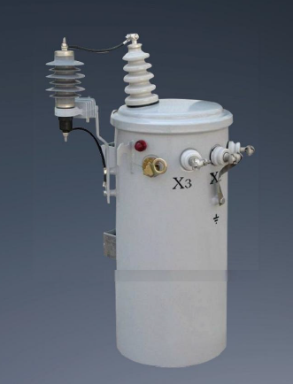
Match kVA ratings precisely to specific facility demands. Avoid excessive over-engineering while maintaining adequate safety margins for future expansion. Accurate sizing prevents thermal overloading and optimizes long-term energy consumption. You must perform a rigorous load study, cataloging every piece of equipment, its duty cycle, and its phase requirements.
A 50 kVA single phase transformer serves light commercial buildings and large residential clusters effectively. Agricultural pumping stations frequently utilize this capacity for deep well irrigation. It provides enough power for moderate lighting loads, standard HVAC systems, and basic commercial machinery. At 240V, a 50 kVA unit delivers approximately 208 amps of secondary current, which easily supports a standard 200A commercial panelboard.
Expect a moderate physical footprint that accommodates heavy-duty wall-mounting brackets or simple floor installations. Standard primary and secondary voltage configurations vary heavily by regional grid standards, but 480V primary to 120/240V secondary is ubiquitous. Thermal management remains straightforward at this level. Ensure adequate ambient ventilation and maintain a minimum of six inches of clearance around the enclosure louvers to facilitate natural convection cooling. Never stack boxes or equipment against the ventilation grilles.
Mid-sized manufacturing facilities and commercial retail spaces demand significantly higher capacity. Heavy-duty irrigation systems and large commercial kitchens often require a 100 kVA single phase transformer. This size handles substantial continuous loads alongside frequent motor starting events. At 240V, this unit outputs over 416 amps, requiring heavy-duty secondary conductors and robust termination lugs.
Installation requirements shift significantly at this tier. Pad-mounting on reinforced concrete becomes much more common than heavy pole-mounting, due to the sheer weight of the core and coil assembly. Harmonic mitigation becomes a critical engineering focus. Non-linear loads at this power level generate substantial internal heat. You must evaluate the facility's harmonic profile and potentially specify a K-rated core to prevent premature insulation failure. We often see standard 100 kVA units fail within five years when subjected to heavy VFD loads without proper K-factor specification.
Specialized industrial machinery requires dedicated, robust power delivery. Large-scale temporary power setups, mining applications, and heavy fabrication shops utilize a 160 kVA single phase transformer. This equipment handles extreme electrical stress, continuous heavy-duty cycles, and massive inrush currents from large single-phase motors.
Deployment involves strict structural and logistical considerations. You will likely need professional crane access, heavy-duty rigging equipment, and engineered reinforced concrete padding. Fault-current calculations are highly critical at 160 kVA. Secondary breaker sizing must perfectly match the elevated short-circuit potential. If the unit has an impedance of 2%, the available fault current on the secondary can exceed 33,000 amps at 240V. The internal bracing of the windings must withstand massive mechanical forces during a downstream fault event, and your secondary switchgear must have an adequate Interrupting Rating (IR).
Capacity (kVA) | Secondary Amperage (240V) | Typical Application | Mounting Style |
|---|---|---|---|
10 kVA | 41.6 A | Control circuits, small lighting | Wall / Panel |
50 kVA | 208.3 A | Light commercial, ag pumps | Wall / Floor |
100 kVA | 416.6 A | Retail, mid-manufacturing | Floor / Pad |
160 kVA | 666.6 A | Heavy industrial, mining | Reinforced Pad |
Connect physical components directly to long-term facility outcomes. Every material choice impacts installation logistics, maintenance requirements, and overall reliability. You must look past the nameplate rating and evaluate the internal construction.
Copper offers superior electrical conductivity and exceptional mechanical strength. It withstands severe short-circuit conditions better than alternative materials due to its high tensile strength. Copper has a lower thermal expansion rate, ensuring tighter electrical connections over decades of thermal cycling. It requires a smaller core window, resulting in a slightly more compact overall footprint. However, it carries a premium upfront cost and adds significant weight to the final assembly, complicating rigging and structural support.
Aluminum presents a much lower cost-to-weight ratio. This significantly eases installation logistics and reduces structural support requirements for pole-mounted or wall-mounted units. Modern manufacturing techniques make aluminum highly reliable, provided installers follow strict termination protocols. Installers must use proper oxide-inhibiting joint compounds (like Noalox) and calibrated torque wrenches. Aluminum exhibits "cold flow" under pressure and expands more than copper when heated. You must use Belleville spring washers on all aluminum lug connections to maintain constant pressure during thermal cycling and prevent catastrophic arc faults.
Dry-type units, including Vacuum Pressure Impregnated (VPI) and Cast Resin models, suit indoor environments perfectly. They eliminate the risk of fluid leaks entirely. They are ideal for fire-sensitive locations like hospitals, schools, and high-rise commercial buildings. VPI units dip the core and coil in a polyester or epoxy resin, baking it to form a solid, moisture-resistant barrier. Cast resin units encapsulate the windings entirely in solid epoxy, offering superior protection against harsh airborne contaminants. However, dry-types require excellent ambient ventilation to dissipate heat effectively and generally have lower overload capacities.
Liquid-filled units utilize mineral oil or less-flammable seed oils (like FR3 ester fluids). They dominate outdoor, high-capacity applications requiring superior dielectric strength. Liquid cooling dissipates heat much more effectively during sustained peak loads, as the fluid circulates through external radiators. They offer better overload capabilities and longer lifespans in harsh weather. However, they require strict spill containment measures, regular fluid sampling, and adherence to environmental regulations regarding oil leaks.
Grain-oriented electrical steel (GOES) serves as the traditional, highly reliable core material. Manufacturers stack these cold-rolled steel laminations precisely to direct the magnetic flux. This construction provides excellent performance for standard commercial applications and meets baseline efficiency regulations.
Amorphous metal cores drastically reduce continuous no-load losses. The rapid cooling process during manufacturing creates a random molecular structure in the metal, which minimizes magnetic friction. Core material directly dictates hysteresis and eddy current losses. Selecting amorphous cores ensures strict compliance with regional energy efficiency mandates and reduces continuous energy waste. While amorphous cores cost more upfront, they run significantly cooler and reduce the base electrical load of the facility.
Primary voltage taps compensate for facility voltage variations. Full Capacity Above Normal (FCAN) and Full Capacity Below Normal (FCBN) taps are essential. They allow technicians to adjust the turns ratio manually. If your utility delivers 495V instead of 480V, you adjust the tap to the +2.5% or +5% position, ensuring the secondary voltage remains at a stable 120/240V. Never adjust taps while the unit is energized.
IoT condition monitoring plays a rapidly growing role in predictive maintenance strategies. Winding temperature indicators (WTI) and liquid level gauges provide real-time operational data. Smart metering prevents unexpected thermal overloads by alerting facility managers before critical thresholds are breached. We recommend installing continuous thermal monitoring on all units above 100 kVA to track load profiles and identify phase imbalances before they cause insulation failure.
Evaluate physical constraints and maintenance requirements long before issuing a purchase order. Hidden installation challenges and poor maintenance strategies ruin otherwise excellent engineering designs. A proactive approach to lifecycle management prevents unexpected downtime.
Site preparation carries significant hidden costs. Dry-type units often require extensive ventilation upgrades to maintain safe ambient temperatures. You may need to install dedicated exhaust fans or expand the HVAC capacity in the electrical room. The NEC requires specific working clearances around the equipment, which can dictate the size of the electrical room itself.
Liquid-filled units mandate strict spill containment measures. You must construct concrete containment berms to catch potential oil leaks, sizing the berm to hold the entire volume of the fluid plus rainwater freeboard. Structural reinforcement is mandatory for heavy 160 kVA units. Ensure your rigging team has adequate forklift or crane access to maneuver the equipment safely into its final position without damaging the cooling fins or bushings.
Never bypass rigorous factory testing. Standard routine tests include ratio verification, polarity checks, and precise no-load loss measurements. These tests confirm the unit matches the baseline engineering specifications and that no internal damage occurred during final assembly.
Type tests verify temperature rise limits and impulse withstand capabilities. Requiring specific IEEE C57.12.00, ANSI, or IEC testing documentation actively mitigates the risk of premature failure. Demand comprehensive test reports before allowing the equipment to ship from the manufacturing facility. For critical infrastructure, send a third-party engineer to witness the FAT in person.
Realistic maintenance extends equipment lifespan significantly. Schedule annual infrared thermography scans to detect loose electrical terminations before they cause arc flashes. Heat signatures reveal failing connections instantly, allowing you to schedule targeted downtime for re-torquing.
Perform oil dissolved gas analysis (DGA) annually for all liquid units. Monitor specific fault gases: elevated hydrogen indicates partial discharge, ethylene points to severe overheating, and acetylene confirms active internal arcing. Conduct routine torque checks on all primary and secondary electrical connections using calibrated tools. Vacuum the louvers and windings of dry-type units annually to remove dust buildup that restricts airflow.
Maintenance Task | Frequency | Target Equipment | Purpose |
|---|---|---|---|
Infrared Thermography | Annually | All Types | Identify loose connections and hot spots |
Dissolved Gas Analysis (DGA) | Annually | Liquid-Filled | Detect internal arcing or paper degradation |
Visual Inspection & Cleaning | Semi-Annually | Dry-Type | Remove dust, ensure clear ventilation |
Torque Verification | Every 3 Years | All Types | Prevent thermal expansion loosening |
Industry lead times vary wildly for custom specifications. Highly specialized voltages, unique physical dimensions, or non-standard impedance requirements can delay projects by several months. Off-the-shelf kVA ratings ship significantly faster.
Standardize your specifications early in the design phase to mitigate costly project delays. Work closely with electrical engineers to utilize standard tap configurations and common enclosure types whenever possible. Order long-lead items immediately after the single-line diagram is approved, rather than waiting for the final building footprint to be finalized.
Conduct a comprehensive load study to capture continuous, non-linear, and inrush demands accurately before selecting a kVA rating.
Verify local environmental codes regarding liquid-filled spill containment or indoor fire ratings to select the correct cooling medium.
Consult with a licensed electrical engineer to validate all fault-current calculations, breaker sizing, and protection coordination.
Submit detailed technical specifications, including required NEMA ratings and winding materials, to your manufacturer to secure an accurate quote.
Establish a baseline maintenance schedule, including annual infrared scanning and DGA testing, immediately upon commissioning the unit.
A: A single phase unit utilizes one primary and one secondary winding to step voltage down for residential or light commercial use. A three phase unit uses three distinct sets of windings to deliver continuous, heavy-duty power for large industrial applications and massive motor loads. Three phase power provides smoother power delivery without the zero-crossing dips inherent in single phase systems.
A: Use the standard formula: kVA = (Volts × Amps) / 1000. Always add a 25% safety margin to this baseline calculation to comply with NEC continuous load requirements. This margin accommodates future load expansion and prevents dangerous thermal overloading during unexpected peak demand periods or heavy motor inrush events.
A: Yes. You can connect a single-phase unit directly across two lines of a three-phase system. This taps a single phase of power for dedicated equipment, such as a 240V machine tool on a 480V three-phase grid. However, you must carefully balance the overall three-phase system loads to prevent dangerous voltage imbalances across the facility.
A: A properly specified and maintained unit typically lasts 20 to 30 years. This lifespan heavily depends on strict adherence to engineered thermal management limits, routine preventative maintenance, clean operating environments, and the complete absence of severe, repeated short-circuit events that physically degrade the winding insulation.
A: Dry-type units completely eliminate the risk of fluid leaks and are inherently safer for indoor installations. They comply easily with strict indoor fire codes, making them the ideal choice for commercial buildings, schools, and sensitive manufacturing environments where a mineral oil fire or spill would be catastrophic.
A: No-load losses, frequently called core losses, occur constantly as long as the primary winding remains energized. These electrical losses happen regardless of whether any secondary load is connected. They are driven entirely by hysteresis and eddy currents within the steel core and represent a continuous energy draw on the facility.
A: Tap changers allow technicians to make minor manual adjustments to the internal turns ratio. This ensures the secondary voltage remains perfectly stable and within equipment tolerances, even when the incoming primary grid voltage fluctuates significantly above or below normal levels. Taps are critical for compensating for utility voltage drop.

