


Views: 0 Author: Site Editor Publish Time: 2026-07-26 Origin: Site


Specifying an incorrectly sized power transformer creates immediate engineering and financial risks. Undersizing leads to catastrophic thermal failure, insulation breakdown, and facility downtime. Oversizing heavily inflates initial capital expenditures and generates persistent no-load losses that drain energy budgets for decades. Facility managers and electrical engineers face a strict balancing act. You must translate facility load profiles, motor starting currents, and power factors into a precise kilovolt-ampere (kVA) requirement. You also need to account for future capacity without overspending. This guide provides a systematic, evidence-based framework for calculating single-phase and three-phase kVA ratings. We will apply necessary safety margins to your raw data. Finally, we will map those calculations to specific transformer architectures to streamline your procurement process.
Formula Baseline: Single-phase kVA requires a straightforward (V × I) / 1000 calculation, whereas three-phase systems must account for the square root of 3 (√3 × V × I) / 1000.
Power Factor Dependency: Real power (kW) must be divided by the facility's Power Factor (PF) to determine the actual apparent power (kVA) the transformer must supply.
Standardization Over Customization: Calculated kVA must be rounded up to the next standard industry size to ensure availability and avoid prohibitive custom manufacturing costs.
Environmental Matching: The calculated kVA dictates the size, but the installation environment dictates the technology (e.g., dry-type for indoors vs. oil-immersed for outdoors).
Understanding the difference between apparent power and real power is the first step in sizing electrical equipment. Real power, measured in kilowatts (kW), represents the actual energy consumed to perform useful work. Apparent power, measured in kilovolt-amperes (kVA), represents the total power supplied to the circuit. Apparent power includes both the real power and the reactive power needed to sustain magnetic fields in inductive loads.
Manufacturers rate transformers in kVA rather than kW for a specific structural reason. A transformer's core and coil thermal limits depend entirely on voltage and current. Voltage dictates the insulation limits. Current dictates the copper losses and resulting heat. The transformer must handle the total current flowing through its windings, regardless of the load's power factor. This contrasts with generator sizing, which often factors in the prime mover's actual kW capacity.
Power factor (PF) plays a massive role in your final calculation. Inductive loads like electric motors, compressors, and HVAC systems lower the facility's power factor. A lower power factor means the system draws more current to deliver the same amount of useful work. You must account for this inefficiency. Use the formula: kVA = kW / PF. If you have a 100 kW load and a power factor of 0.8, your transformer must supply 125 kVA.
Different facilities exhibit vastly different baseline power factors based on their equipment:
Heavy manufacturing plants with large induction motors: 0.70 to 0.80 PF.
Commercial office buildings with modern HVAC and LED lighting: 0.85 to 0.90 PF.
Data centers with power factor corrected UPS systems: 0.95 to 0.99 PF.
Residential complexes with mixed appliance loads: 0.80 to 0.90 PF.
A successfully sized transformer meets several strict criteria. It operates comfortably at 70% to 80% of its maximum capacity during normal conditions. This range maintains optimal electrical efficiency. It also ensures the core and coil stay well within their thermal limits during peak seasonal loads or temporary operational spikes.
Single-phase transformers serve residential networks, rural distribution lines, and isolated commercial loads. When calculating kVA, you must decide whether to use primary or secondary voltage. Because kVA remains constant across the transformer (ignoring negligible efficiency losses), standard engineering practice uses the secondary voltage and secondary current. The secondary side represents the actual load demand.
The single-phase formula is highly straightforward. You multiply the load voltage by the load current and divide by one thousand. The exact calculation is: kVA = (Load Voltage × Load Current) / 1000.
Consider a realistic scenario. You need to power a remote pumping station. The equipment requires a 240V single-phase supply and draws a maximum continuous current of 150 Amps. You multiply 240 by 150 to get 36,000 volt-amperes. Divide that by 1000. Your raw calculation requires a 36 kVA capacity.
Single-phase sizing applies heavily to specific isolated loads where running three-phase lines is economically unviable. Rural electrification projects rely entirely on accurate single-phase calculations to minimize line losses over long distances. You must evaluate the specific load profile of the site before finalizing the calculation.
Application Type | Load Voltage (V) | Max Current (A) | Calculated Base kVA |
|---|---|---|---|
Rural Irrigation Pump | 240 | 100 | 24.0 kVA |
Small Commercial Shop | 120 | 200 | 24.0 kVA |
Residential Block | 240 | 300 | 72.0 kVA |
Telecom Cell Tower | 120 | 150 | 18.0 kVA |
For these specific applications, the D11-M(R) Single-Phase Power Transformer serves as an excellent benchmark solution. It aligns perfectly with low-loss, high-efficiency distribution networks. Its wound core design reduces no-load losses significantly, making it ideal for rural grids where loads fluctuate drastically throughout the day.
Industrial facilities, large commercial buildings, and manufacturing plants utilize three-phase power. Three-phase calculations require an additional multiplier to account for the phase angle difference in alternating current systems. The three-phase formula is: kVA = (√3 × Line-to-Line Voltage × Current) / 1000. The square root of 3 is approximately 1.732.
Let us walk through an industrial calculation. A manufacturing floor requires a 480V three-phase supply. The combined equipment draws 400 Amps. You multiply 1.732 by 480 by 400. This equals 332,544 volt-amperes. Divide by 1000. Your raw requirement is 332.5 kVA.
Handling complex loads requires a methodical approach. Industrial facilities rarely have a single massive load. They have dozens of mixed loads. You must calculate the kVA for every individual three-phase and single-phase load connected to the downstream panels. Once you calculate the individual kVA for lighting, HVAC, and machinery, you sum them together to find the total facility demand.
Inventory all continuous loads, such as lighting and server racks, and calculate their individual kVA.
Identify all non-continuous loads, such as intermittent welding machines or hoists, and apply a demand factor based on their duty cycle.
Calculate the kVA for the largest single motor load separately to account for its specific inrush current requirements.
Sum the continuous loads, the factored non-continuous loads, and the largest motor load to establish the baseline facility demand.
Motor starting currents present the biggest sizing challenge. Electric motors require massive energy spikes to overcome inertia during startup. This is known as Locked Rotor Amps (LRA) or inrush current. Startup demands can temporarily exceed steady-state kVA by 500% to 700%. If you size the transformer strictly for running amps, the voltage will drop severely during motor startup. This voltage sag causes contactors to chatter and equipment to trip offline. You must apply an inrush multiplier for heavy motor loads to ensure the transformer has enough magnetic flux capacity to handle the spike without dropping voltage.
Running a transformer at 100% capacity continuously degrades the cellulose paper insulation inside the coils. Heat is the primary enemy of transformer longevity. The industry-standard practice dictates adding a 20% to 25% safety margin to your final calculated kVA. This buffer prevents continuous maximum operation. It protects the core and coil from thermal degradation and extends the equipment lifespan by decades.
Environmental extremes force further adjustments. Standard transformers are rated for operation below 1000 meters in altitude and at maximum ambient temperatures of 40°C. High altitudes feature thinner air, which reduces the cooling efficiency of radiators and cooling fans. Extreme ambient temperatures prevent the transformer from shedding internal heat. If you install equipment in these conditions, you must derate the transformer. Derating forces you to select a higher kVA baseline to compensate for the reduced cooling capacity.
Installation Altitude (Meters) | Cooling Efficiency Loss | Required kVA Derating Factor |
|---|---|---|
Sea Level to 1000m | 0% | 1.00 (No Derating) |
1500m | 5% | 0.95 |
2000m | 10% | 0.90 |
3000m | 20% | 0.80 |
Calculated kVA values rarely match what manufacturers build. You must round your final number to a standard industry size. If your calculation plus safety margin equals 615 kVA, you cannot order a 615 kVA unit. You must round up to the nearest standard size. Ordering custom sizes incurs massive engineering fees and delays projects by months.
Standard Three-Phase kVA Ratings | Typical Application Scale |
|---|---|
150 kVA - 300 kVA | Light Commercial, Small Clinics, Retail |
500 kVA - 750 kVA | Mid-Size Manufacturing, Office Buildings |
1000 kVA - 1500 kVA | Heavy Industrial, Data Centers, Hospitals |
2000 kVA - 3000 kVA | Grid Substations, Massive Industrial Plants |
Once you calculate the final kVA, the physical footprint and site safety requirements dictate the actual transformer type you purchase. The evaluation dimension strictly comes down to indoor versus outdoor deployment.
High-capacity, outdoor applications generally utilize oil-filled transformers. Mineral oil provides superior dielectric strength and exceptional cooling properties. Outdoor environments offer unrestricted space, allowing for large radiator banks. Oil-filled units handle massive kVA requirements efficiently and cost-effectively. They dissipate heat rapidly, which is critical when running near the upper limits of your calculated kVA.
For these demanding environments, the S20-M Oil-Immersed Power Transformer provides a highly efficient, hermetically sealed option. The sealed design prevents oxygen and moisture from contaminating the oil. This architecture is ideal for grid-level loads, harsh outdoor weather, and heavy industrial yards where cooling efficiency is paramount.
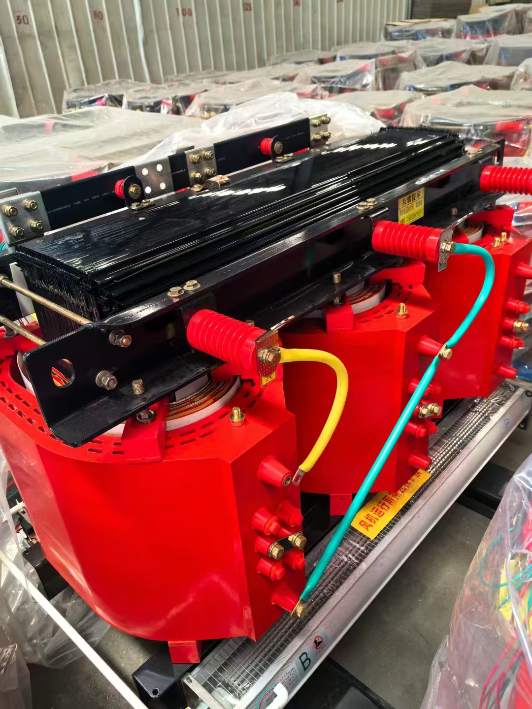
Indoor applications require entirely different technology. Commercial high-rises, underground vaults, and indoor manufacturing floors have strict fire codes. Mineral oil poses a severe fire and environmental hazard indoors. You must specify dry-type transformers for these locations. Dry-type units use air for cooling and cast resin to protect the coils. They rely on natural air convection or forced air fans to manage the heat generated by the kVA load.
The SCB14 Dry-Type Power Transformer stands as the standard for high-safety, low-maintenance indoor applications. Its cast-resin design handles thermal stress exceptionally well while completely eliminating fire risks and oil leak hazards. It meets strict indoor building codes while delivering the required kVA.
Procurement involves balancing initial capital expenditures against long-term operational efficiency. Buying a slightly oversized transformer increases your initial purchase cost. It also increases the no-load losses, as a larger core requires more energy to stay magnetized 24/7. However, running a perfectly sized transformer near peak capacity increases load losses (copper losses) and drastically shortens the equipment's lifespan due to heat. Engineers typically favor slight oversizing to guarantee reliability and accommodate future facility expansion.
Lead times present a massive project risk. Specifying non-standard kVA ratings or highly customized impedance values extends procurement lead times by months. Standard sizes like 1000 kVA or 1500 kVA are often stocked or have established production lines. Custom units require fresh engineering drawings, custom core cutting, and unique testing protocols. Always stick to standard kVA ratings to keep construction schedules intact.
Modern facilities face harmonic distortion. Non-linear loads like variable frequency drives (VFDs), LED lighting networks, and server racks generate harmonics. These harmonics distort the electrical sine wave and create excess heat inside the transformer windings. A standard kVA upsize will not solve harmonic heating. You must specify a K-factor rated transformer. K-factor units feature heavier copper windings and specialized core designs to mitigate harmonic heat while delivering the calculated kVA.
K-1: Standard rating for linear loads like basic heating and incandescent lighting.
K-4: Suitable for facilities with up to 50% non-linear loads, such as standard office buildings.
K-13: Designed for heavy telecom, data centers, and industrial floors with multiple VFDs.
K-20: Reserved for extreme harmonic environments with massive server farms or specialized medical imaging equipment.
Precise kVA calculation remains a non-negotiable first step in power system design. You cannot guess your facility's power requirements. You must gather accurate load data, assess your power factor, and strictly adhere to thermal safety margins to ensure grid reliability.
The shortlisting logic follows a strict path. First, calculate the base load using the correct single-phase or three-phase formula. Second, apply power factor corrections and a 25% safety margin. Third, round up to the nearest standard industry size. Finally, select the appropriate technology based on site constraints: D11-M(R) for single-phase networks, S20-M for outdoor oil applications, or SCB14 for indoor dry-type requirements.
Take the following actions to finalize your equipment selection:
Audit your facility's single-line diagram to catalog all existing and planned electrical loads.
Consult with a licensed electrical engineer to verify your load profiles and calculate exact motor inrush demands.
Measure your facility's actual power factor at the main switchgear using a power quality analyzer.
Contact a manufacturer to request specification sheets, dimensional drawings, and lead times for standard kVA units.
A: Engineers apply a 20% to 25% safety margin to the final calculated load. This buffer prevents the transformer from running continuously at maximum capacity. It protects the internal cellulose insulation from thermal degradation, accommodates unexpected peak loads, and allows for future facility expansion without requiring immediate equipment replacement.
A: You convert real power (kW) to apparent power (kVA) by dividing the kW by the facility's Power Factor (PF). The formula is kVA = kW / PF. If you do not know the exact power factor, using 0.8 is a common, conservative estimate for industrial environments with heavy motor loads.
A: You standardly use the secondary (load) voltage and secondary current for calculations. Because kVA remains constant across both the primary and secondary sides of the transformer, measuring the actual downstream load demand on the secondary side provides the most accurate sizing metric.
A: An undersized transformer will overheat rapidly. This excess heat degrades the internal insulation, leading to internal short circuits. It also causes severe voltage drops during high demand or motor startups, which damages connected equipment and eventually results in catastrophic transformer failure.
A: No. The base mathematical formulas for calculating kVA remain identical regardless of the cooling medium. You calculate the required power using the same voltage and current metrics. The choice between dry-type and oil-immersed depends entirely on physical location, fire codes, and environmental constraints, not the kVA math.

