


Views: 0 Author: Site Editor Publish Time: 2026-08-21 Origin: Site


Electrical infrastructure carries high stakes. Installing a transformer dictates the safety, reliability, and code compliance of your facility's power supply. Facility managers and agricultural operators often lack the technical oversight framework required for this process. Missteps in site preparation lead to premature equipment failure. Poor load calculations cause severe safety hazards. Contractor selection errors result in regulatory fines. Installation complexity varies wildly depending on your site. Integrating a unit into new construction differs entirely from retrofitting existing facilities. Space constraints complicate retrofits significantly. This guide serves as a comprehensive oversight manual. It provides the necessary technical vocabulary and procedural roadmap to procure equipment confidently. We cover managing certified electrical contractors and ensuring a compliant installation lifecycle. You will learn how to handle everything from the first site walk-through to the final sign-off.
Professional Execution is Non-Negotiable: Installation must be performed by a licensed, certified electrician to meet National Electrical Code (NEC) and local utility standards.
Application Dictates Specification: Proper sizing (nominal power) and environmental ratings are critical, whether deploying a single phase transformer for small commercial use or ruggedized units for agricultural needs.
Site Preparation Drives Longevity: Adequate ventilation, structural anchoring (pads or poles), and rigorous grounding protocols are foundational to preventing thermal overload and electrical faults.
Verification Precedes Energization: Comprehensive pre-energization testing (e.g., insulation resistance, tap setting verification) is required before the system goes live.
Calculating nominal power requires a strict audit of the total connected load. You must identify every piece of equipment drawing power on the secondary side. Total the wattage or volt-amperes (VA) for all devices. Separate continuous loads from non-continuous loads. Continuous loads operate for three hours or more at maximum current. The National Electrical Code requires sizing continuous loads at 125 percent of their actual draw. This prevents thermal degradation of the winding insulation over time. Factor in future capacity expansion. Adding a 20 percent buffer prevents undersizing when facility needs grow.
Consider a practical field example. You have 15,000 VA of continuous lighting load and 10,000 VA of non-continuous receptacle load. Multiply the 15,000 VA by 1.25 to get 18,750 VA. Add the 10,000 VA for a total of 28,750 VA. Adding a 20 percent future expansion buffer brings your requirement to 34,500 VA, or 34.5 kVA. You would select a standard 37.5 kVA unit to handle this demand safely.
Power factor heavily impacts efficiency and sizing. It represents the ratio of real power to apparent power. Inductive loads like motors, compressors, and heavy HVAC equipment lower the power factor. A low power factor means the system draws more current to perform the same work. A 10 kW motor with a 0.8 power factor actually draws 12.5 kVA. Sizing based solely on kilowatts (kW) leads to overloaded equipment. A successful procurement matches primary and secondary voltage ratings exactly. It secures the appropriate kVA rating and specifies the correct impedance to limit short-circuit currents.
Form factors matter when selecting a single phase transformer for small commercial use. Low voltage dry-type units fit well in retail spaces, small offices, and indoor utility rooms. These environments prioritize indoor safety and space conservation. Dry-type units eliminate the fire risks and containment requirements associated with liquid-filled models. Pay close attention to NEMA sound level constraints. Acoustic noise disrupts commercial operations. Select units with factory-installed vibration isolation pads and low decibel ratings for indoor retrofits. Specify Class 220 insulation with a 150-degree Celsius temperature rise for maximum durability in commercial settings.
Agricultural environments demand ruggedized equipment. Deploying a single phase transformer for irrigation pump requires specific performance capabilities. Irrigation pumps generate massive inrush currents during motor startup. The core and coil assembly must handle these temporary overloads without causing severe voltage sags on the line. Weather-resistant NEMA enclosures protect internal components from harsh farm conditions. NEMA 3R or NEMA 4X stainless steel ratings shield the unit from rain, sleet, corrosive fertilizers, and airborne agricultural dust.
Regulatory compliance dictates equipment legality. Underwriters Laboratories (UL) listing ensures baseline safety testing. American National Standards Institute (ANSI) standards govern construction and performance metrics. Department of Energy (DOE) efficiency mandates require specific energy conservation levels. Modern units must meet DOE 2016 efficiency standards. Manufacturers achieve this by using high-grade grain-oriented electrical steel for the core. This reduces no-load losses, limits heat generation, and lowers long-term operational costs.
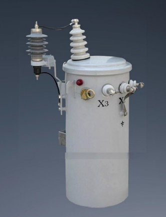
Clearance and ventilation dictate equipment lifespan. Standard clearance requires at least six inches of space between the unit and adjacent walls. Many manufacturers mandate twelve inches for larger kVA ratings. This ensures adequate airflow around the enclosure louvers. Restricted airflow causes thermal degradation. Heat buildup destroys winding insulation rapidly. Always consult the manufacturer nameplate for specific clearance metrics. For indoor utility rooms, calculate the required cubic feet per minute (CFM) of exhaust ventilation to remove the heat generated by the unit at full load.
Environmental hazards require immediate mitigation. Indoor units face dust and moisture accumulation. Outdoor units battle corrosive elements, extreme weather, and wildlife intrusion. Select the appropriate NEMA enclosure based on the installation environment. Retrofitting older units in existing buildings presents logistical hurdles. Routing new conduit through constrained spaces requires precise planning. Existing structural support may lack the load-bearing capacity for modern, heavier units. Structural engineers must verify floor load limits before placing heavy dry-type units on elevated concrete slabs. Verify doorway dimensions and freight elevator capacities before delivery. Many retrofits fail because the unit simply cannot fit through existing architectural pathways.
Concrete pad installations differ vastly from utility pole mounting. Pad-mounted units require a level, reinforced concrete base. Pour a 3000 PSI concrete pad with a #4 rebar grid. The pad must extend at least twelve inches beyond the equipment footprint. This prevents soil erosion from undermining the base and provides a working surface for technicians. Chamfer the edges of the pad to prevent concrete spalling. Allow the concrete to cure fully before setting the equipment. Pole-mounted installations require heavy-duty utility poles. The pole must withstand the sheer weight and wind load of the equipment. Rot or structural fatigue in existing poles mandates immediate replacement before hanging new hardware.
Specific fixation hardware ensures mechanical stability. Support lugs and heavy-duty hooks secure the enclosure to the mounting surface. Vibration-isolating mounting pads reduce acoustic noise. They also minimize mechanical stress on internal connections. Seismic zones require specialized anchoring systems. You must use engineered expansion anchors and seismic brackets to prevent equipment displacement during ground tremors.
Mounting Type | Primary Hardware Required | Key Structural Consideration |
|---|---|---|
Concrete Pad | Expansion anchors, leveling shims, #4 rebar | Soil compaction, pad thickness, drainage slope |
Utility Pole | Support lugs, through-bolts, cross-arm brackets | Pole integrity, wind load, weight distribution |
Indoor Floor | Vibration isolators, wedge anchors | Floor load capacity, acoustic dampening |
Wall Mount | Heavy-duty brackets, structural lag bolts | Wall stud integrity, sheer weight limits |
Transporting heavy electrical equipment off-grid presents logistical challenges. A single phase transformer for remote areas often requires specialized rigging. Rough terrain complicates delivery. Site access may require temporary road reinforcement or track-mounted lifting equipment. Plan delivery routes carefully to avoid low bridges, weight-restricted roads, or soft ground that could trap delivery trucks. In extreme cases, mountain top communication sites require helicopter drops.
Infrastructure adaptations make remote installations viable. Single-phase wiring requires fewer support structures. It uses less conductor material than three-phase systems. This makes it cost-effective for long-distance distribution. Utility companies often run single-phase lines to remote agricultural, mining, or telecommunication sites. Three-phase power remains unavailable or prohibitively expensive to run across miles of empty terrain. Single Wire Earth Return (SWER) systems sometimes utilize these units to provide power over vast distances with minimal infrastructure.
Perform a rigorous visual inspection upon receiving the unit. Check for shipping damage immediately. Look at the shock watch indicators on the shipping crate. Inspect the integrity of the enclosure and weather seals. Look for dents, scratches, or oil leaks in liquid-filled models. Verify the configuration of the high voltage bushings. ANSI standards dictate specific bushing layouts. Ensure the delivered unit matches the approved submittal drawings and nameplate data exactly.
Safe rigging prevents catastrophic accidents. Use designated lifting hooks and spreader bars. Spreader bars prevent the lifting slings from crushing the sheet metal enclosure. Never lift a unit by its radiators, bushings, or conduit boxes. Hoists must exceed the total weight of the unit. Maintain proper weight distribution during the lift. Center the hoist directly over the unit's center of gravity. Improper handling causes internal shifting. This damages core assemblies, breaks internal connections, and ruins the equipment before installation.
Conductor sizing depends entirely on ampacity ratings. Use correctly sized copper or aluminum cables for primary and secondary connections based on NEC Article 310 ampacity tables. Undersized conductors overheat and cause electrical fires. Route cables neatly through designated conduit entries. Apply pulling compound to avoid damaging cable insulation during long conduit runs. Maintain physical separation between high-voltage and low-voltage conductors inside the enclosure.
When terminating conductors, use the correct compression lugs or mechanical lugs specified by the manufacturer. Apply a thin layer of oxide-inhibiting joint compound on aluminum conductors before termination to prevent galvanic corrosion. Ensure the wire bending space inside the enclosure complies with NEC Article 312.6. Tight radius bends stress the insulation and lead to dielectric breakdown over time.
Electricians adjust primary tap settings to match incoming utility voltage. Utility voltage often fluctuates from nominal ratings. If the utility supplies 490V instead of 480V, the secondary output will run high. High secondary voltage damages sensitive electronic equipment. Adjusting the primary taps compensates for this variance. You move the internal jumpers to the Full Capacity Above Normal (FCAN) or Full Capacity Below Normal (FCBN) positions. This ensures the secondary voltage output remains within acceptable tolerances.
Tighten all electrical connections to the manufacturer's specified torque. Use a calibrated torque wrench. Mark each torqued bolt with a paint pen to verify completion. Loose connections cause electrical arcing. Arcing generates massive heat and destroys terminal blocks. Over-tightening strips threads and damages conductors. Follow the torque values listed on the equipment nameplate exactly.
Mandate strict arc flash safety protocols. Personnel must wear appropriate Personal Protective Equipment (PPE) based on the calculated incident energy. Adhere to NFPA 70E safety standards during wiring. De-energize all circuits before making connections. Implement lockout/tagout (LOTO) procedures. Never assume a circuit is dead without verifying it with a calibrated multimeter.
Differentiate between system grounding and equipment grounding. System grounding connects the neutral terminal to the earth. This stabilizes voltage during normal operation and establishes a zero-voltage reference point. Equipment grounding connects the metal enclosure to the earth. This provides a safe path for fault current. It prevents the enclosure from becoming energized during a short circuit, protecting personnel from fatal shocks.
Install grounding devices per NEC Article 250. Drive copper-clad grounding rods deep into the earth. Use exothermic welding, like Cadweld, to make permanent, corrosion-resistant connections to the ground rods. Connect system bonding jumpers between the enclosure and the grounding electrode system. Size the Equipment Grounding Conductor (EGC) based on the overcurrent protection device. Verify ground fault paths using an earth ground resistance tester. You want a resistance to ground of 25 ohms or less. Low impedance paths ensure breakers trip instantly during a fault.
Verify winding insulation integrity before applying power. Perform an insulation resistance test using a Megger. Ensure the unit is completely disconnected from the line and load sides. A residual connection will skew your readings. Apply a 1000V DC voltage across the windings for one minute. Test primary to ground, secondary to ground, and primary to secondary. Measure the resistance in megohms. You want readings well above 100 megohms. Low resistance indicates moisture ingress, dirt, or damaged insulation. Never energize a single phase transformer that fails a Megger test.
Execute turns ratio and continuity checks. A Transformer Turns Ratio (TTR) tester verifies internal connections. Apply the test voltage to the high-voltage winding and measure the induced voltage on the low-voltage winding. The measured ratio must be within 0.5 percent of the calculated nameplate ratio. Any deviation beyond this tolerance indicates shorted turns or a defective tap changer. Continuity checks verify that no internal windings broke during transit. Document all test results for the final commissioning report.
Coordinate with the local Authority Having Jurisdiction (AHJ). Local electrical inspectors must review the installation. They verify code compliance, clearance metrics, and safety standards. Do not energize the system without AHJ approval. The inspector will check your torque marks, grounding connections, and conductor sizing.
Compile all acceptance papers for project handover. Provide the facility manager with factory test reports and field commissioning data. Submit warranty registrations immediately. Hand over the as-built electrical drawings showing the exact conduit routing and wire sizes. Establish a baseline maintenance schedule. Routine maintenance includes annual infrared thermography and visual inspections. Proper documentation ensures long-term operational success and simplifies future troubleshooting.
Installing units in confined spaces creates severe overheating risks. Heat dissipation fails without adequate airflow. Ambient temperatures rise rapidly inside electrical closets. This degrades winding insulation and shortens equipment life. Thermal overload eventually causes catastrophic failure, leading to unplanned facility downtime.
Strict adherence to manufacturer clearance guidelines mitigates this risk. Never block ventilation louvers with storage boxes or other equipment. Install active ventilation systems if ambient temperatures exceed baseline ratings. Exhaust fans and intake louvers regulate room temperature. Monitor ambient heat levels during peak load conditions to ensure the cooling system keeps up with the heat rejection.
Loose neutral connections create dangerous power quality issues. Inadequate ground loops lead to floating neutrals. A floating neutral causes erratic voltage spikes across the secondary phases. These spikes destroy connected electronic equipment, lighting ballasts, and motor drives. Improper grounding also creates severe shock hazards for personnel touching the enclosure.
Mandate third-party verification of grounding impedance. Use specialized testing firms to confirm ground resistance meets NEC standards. Conduct routine thermal imaging of connections post-installation. Infrared cameras detect loose connections before they fail by showing abnormal heat signatures. Tighten any connections showing elevated temperatures immediately during scheduled maintenance windows.
The physical installation of electrical infrastructure remains a high-risk, highly regulated engineering task. Precision dictates safety and long-term reliability. Select electrical contractors based on specific field experience. Demand verifiable licensing and a proven track record of code compliance. Commercial and agricultural installations require different skill sets, so match the contractor to your specific operational environment to ensure a successful deployment.
Finalize your total connected load calculations, including a 20 percent future capacity buffer.
Consult with a licensed electrical engineer to verify your primary and secondary voltage requirements.
Audit your installation site for structural integrity, clearance, and ventilation constraints.
Begin the procurement process by requesting submittal drawings for the appropriately sized unit.
A: No. Installation requires a licensed, certified electrician. The process involves high-voltage connections, strict National Electrical Code (NEC) compliance, and precise load calculations. DIY installation creates severe fire risks, arc flash hazards, and invalidates equipment warranties. Local utility companies and inspectors will reject uncertified work.
A: Standard baseline clearance is typically six inches from adjacent walls and equipment. However, some manufacturers require up to twelve inches to ensure proper airflow and heat dissipation. Always defer to the specific manufacturer nameplate and local NEC codes for exact clearance mandates.
A: Distribution transformers are typically liquid-filled, pole-mounted, or pad-mounted units used by utilities to step down medium voltage for local grids. Low voltage dry-type transformers are air-cooled, indoor units used inside commercial buildings to step down voltage for specific facility equipment.
A: Calculate your total connected load in volt-amperes (VA). Multiply the voltage by the amperage of all connected devices. Convert this to kilovolt-amperes (kVA). Multiply continuous loads by 1.25 per NEC rules. Add a 20 percent safety margin for future capacity expansion to determine the final size.
A: Primary tap settings compensate for consistently high or low incoming utility voltage. If the utility voltage deviates from the nominal rating, adjusting the taps ensures the transformer provides a stable, accurate secondary output voltage. This protects connected equipment from overvoltage or undervoltage damage.
A: NEC standards require both system grounding and equipment grounding. System grounding connects the neutral terminal to the earth to stabilize voltage. Equipment grounding bonds the metal enclosure to the earth. This provides a safe fault current path, preventing the enclosure from becoming dangerously energized.

