


Views: 0 Author: Site Editor Publish Time: 2026-07-31 Origin: Site


Precise voltage regulation and reliable power transmission form the non-negotiable backbone of utility, industrial, and commercial infrastructure. Specifying the wrong power transformer leads to cascading failures, severe efficiency losses, and strict compliance breaches. Navigating the procurement process requires a rigorous evaluation of voltage classes, cooling methods, phase configurations, and mounting form factors. Equipment mismatches directly compromise grid stability and endanger sensitive downstream components. This guide breaks down how to align technical specifications with operational environments to ensure optimal performance and safety. We explore various insulation types, functional configurations, and site-specific installation requirements. You will learn how to match phase and voltage ratings directly to your unique load profile. By mastering these core engineering principles, facility managers and system operators can prevent system bottlenecks and effectively future-proof their electrical infrastructure.
Align Insulation with Environment: The choice between oil-immersed and dry-type units dictates fire safety protocols, maintenance schedules, and spatial requirements.
Evaluate Total Cost of Ownership (TCO): Initial capital expenditure (CapEx) must be weighed against operational expenditure (OpEx), specifically focusing on energy efficiency, lifespan, and maintenance demands.
Match Phase and Voltage to Load: Selecting specific configurations, such as a 35kV or 10kV unit, requires precise alignment with grid infrastructure and end-user load profiles to prevent system bottlenecks.
Factor in Modern Grid Demands: Integrating smart transformer capabilities and specialized functional designs (like isolation or autotransformers) is critical for future-proofing infrastructure.
Selecting the correct electrical equipment requires a comprehensive understanding of site-specific operational demands. Engineers must balance electrical capacity with physical site constraints and strict safety regulations. A methodical approach prevents premature equipment degradation and ensures long-term operational stability across the entire facility.
Accurate capacity planning begins with calculating the maximum continuous operating voltage (MCOV) and anticipated peak load demands. Engineers analyze historical load profiles and project future energy requirements based on facility expansion plans. You must account for harmonic currents generated by non-linear loads, which significantly increase internal heating within the windings. Over-sizing the unit leads to excessive no-load core losses, while under-sizing risks catastrophic thermal failure during peak demand periods.
Effective load calculation involves several specific engineering steps:
Analyze the steady-state power consumption of all connected downstream equipment using single-line diagrams.
Calculate the transient inrush currents required for starting large industrial motors across the line.
Determine the necessary safety margins for unexpected load spikes during seasonal production peaks.
Evaluate the impact of ambient temperature variations on the equipment's peak load handling capabilities.
Assess the facility's long-term expansion plans to ensure adequate scalability without requiring immediate replacement.
The installation environment dictates fundamental design parameters and enclosure ratings. Indoor installations typically require stringent fire safety measures, robust forced-air ventilation systems, and specific door clearances for rigging. Outdoor installations demand high-grade weatherproofing, UV-resistant polyurethane coatings, and robust lightning protection systems. You evaluate the physical footprint available, ensuring adequate clearance for cooling airflow and routine maintenance access.
Altitude significantly impacts cooling efficiency. Installations above 1,000 meters experience reduced air density, which diminishes the effectiveness of natural convection cooling. Engineers apply specific altitude derating factors to ensure the unit maintains its rated capacity without exceeding permissible temperature rises. High-humidity environments require specialized anti-condensation heaters within the control cabinets to prevent control circuit shorts.
Installation Altitude (Meters) | Cooling Efficiency Loss | Required Derating Factor | Dielectric Strength Reduction |
|---|---|---|---|
Sea Level to 1,000m | 0% | 1.00 (No Derating) | 0% |
1,001m to 1,500m | 5% | 0.95 | 3% |
1,501m to 2,000m | 10% | 0.90 | 6% |
2,001m to 3,000m | 20% | 0.80 | 10% |
Adherence to international electrical standards guarantees operational safety and equipment reliability. You navigate complex frameworks established by organizations like IEEE, IEC, and ANSI. These standards define rigorous testing protocols for dielectric strength, short-circuit withstand capability, and maximum allowable thermal limits. Compliance ensures the equipment safely endures severe electrical faults and environmental stress without rupturing or catching fire.
Key regulatory parameters include:
Basic Impulse Level (BIL) ratings for lightning and switching surge protection on exposed overhead lines.
Short-circuit mechanical withstand limits to prevent winding deformation during severe phase-to-ground faults.
Temperature rise limits for insulating materials under continuous full-load operation.
Acoustic noise emission thresholds for installations located near residential or commercial zones.
Seismic qualification standards for regions prone to earthquake activity, requiring reinforced anchoring.
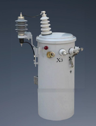
Insulation and cooling methodologies fundamentally define a unit's operational characteristics. The primary cooling medium directly influences thermal dissipation efficiency, physical dimensions, and required maintenance protocols. Understanding these distinctions allows you to match the equipment to its intended operating environment accurately.
These units utilize highly refined mineral oil, synthetic ester fluids, or silicone-based liquids to achieve superior dielectric strength and exceptional thermal dissipation. The fluid circulates through the core and windings, absorbing heat and transferring it to external cooling radiators. This highly efficient cooling mechanism allows for compact designs with exceptionally high power ratings. Manufacturers often equip these units with Buchholz relays to detect internal gas generation and silica gel breathers to prevent moisture ingress during thermal cycling.
Evaluating the 35kV Oil-Immersed Power Transformer reveals its ideal suitability for outdoor substations, expansive utility grids, and high-capacity industrial manufacturing plants. These units handle massive power loads reliably under harsh environmental conditions. The robust sealed tank design protects internal components from moisture ingress, dust, and atmospheric contaminants.
Liquid cooling introduces specific operational trade-offs. Facility managers implement strict environmental containment measures, including secondary spill catchments and concrete moats, to mitigate potential leak risks. Routine maintenance requires regular dissolved gas analysis (DGA) to monitor fluid health and detect early signs of internal arcing or thermal degradation. The presence of combustible fluids necessitates rigorous fire suppression infrastructure, such as deluge systems or blast walls.
Dry-type designs eliminate liquid coolants entirely, relying instead on ambient air for thermal dissipation. Manufacturers utilize cast resin or vacuum pressure impregnated (VPI) technologies to encapsulate the windings. This solid insulation provides excellent mechanical strength and protects the conductors from environmental moisture, chemical exposure, and physical impacts. Class F and Class H insulation systems allow these units to operate safely at higher internal temperatures than their liquid-filled counterparts.
Evaluating the 35kV Dry-Type Power Transformer demonstrates its essential role in indoor commercial facilities, underground transit systems, and environmentally sensitive ecological zones. The absence of combustible fluids fundamentally eliminates fire hazards and environmental contamination risks. These units are frequently installed directly adjacent to the electrical load inside the facility, minimizing secondary cable runs and reducing voltage drop.
The primary trade-off involves physical size and thermal capacity. Air is a less efficient cooling medium than oil, resulting in a larger physical footprint for equivalent kVA ratings. Dry-type units generally exhibit lower overload capacities and require well-ventilated installation spaces to prevent localized overheating. Maintenance is simpler, primarily involving routine visual inspections, infrared thermography scans, and periodic vacuuming of the ventilation ducts to remove dust accumulation.

Electrical networks utilize diverse configurations to optimize power delivery for specific applications. Phase counts, voltage transformation ratios, and specialized internal wiring architectures determine how the equipment interacts with the broader grid. Selecting the correct classification ensures seamless integration and maximum system efficiency.
Three-phase systems dominate heavy industrial and utility-scale transmission networks. This configuration utilizes three alternating currents, offset by 120 degrees, to deliver continuous, uninterrupted power. Three-phase units offer superior material efficiency, requiring significantly less copper and core steel per kVA compared to equivalent single-phase banks. They are essential for operating large industrial motors, heavy manufacturing machinery, and commercial HVAC systems.
Evaluating the 10kV Single-Phase Power Transformer highlights its strategic value in specific niche applications. These units are critical for rural electrification projects, railway traction networks, and isolated residential distribution. They serve unbalanced industrial loads where running extensive three-phase infrastructure is geographically or operationally unfeasible. Single-phase units are lighter, easier to transport, and simpler to mount on standard utility poles using basic rigging equipment.
Voltage transformation is the fundamental purpose of this equipment. Step-up configurations, often called generator step-up (GSU) transformers, are located directly at power generation stations. They elevate the relatively low generation voltage to extremely high transmission levels. This high-voltage transmission drastically reduces electrical current, thereby minimizing resistive line losses over long geographical distances.
Transmission and distribution networks rely heavily on step-down configurations. These units are positioned at regional substations and localized facility entry points. They systematically reduce the high transmission voltages to safe, usable levels for industrial switchgear and commercial lighting circuits. Step-down units ensure that end-user equipment receives the precise voltage required for safe operation without exceeding insulation ratings.
Standard designs provide basic voltage transformation, but specific applications require highly specialized internal architectures. These functional classifications address unique grid challenges, offering targeted solutions for voltage regulation, circuit decoupling, and harmonic mitigation.
Key specialized classifications include:
Autotransformers: These units utilize a single continuous winding that acts as both the primary and secondary circuit. They offer highly compact and efficient voltage regulation for interconnected systems where electrical isolation is not strictly required.
Isolation Transformers: These designs feature physically separated primary and secondary windings. They decouple circuits, protecting sensitive data center servers and medical equipment from dangerous voltage spikes, transient surges, and disruptive ground loops.
Grounding Transformers: Used to create a neutral point in a three-phase ungrounded system, allowing for safe fault current dissipation into the earth.
Rectifier Transformers: Specifically designed to feed large diode or thyristor rectifier circuits, commonly used in aluminum smelting and heavy chemical processing facilities.
Transformer Type | Primary Application | Key Advantage | Main Limitation |
|---|---|---|---|
Autotransformer | Grid interconnection, voltage regulation | High efficiency, smaller physical size | Lacks electrical isolation between circuits |
Isolation | Data centers, sensitive electronics | Blocks voltage spikes and ground loops | Heavier and larger than autotransformers |
Grounding | Ungrounded delta systems | Provides a safe path for fault currents | Only operates during fault conditions |
Rectifier | Smelting, chemical processing | Handles severe DC load stresses | Requires complex harmonic filtering |
Different industries impose unique stresses on electrical infrastructure. A unit designed for a quiet commercial building fails rapidly if deployed in a heavy manufacturing plant. Engineers evaluate specific operational dimensions, including fault tolerance, harmonic distortion, and digital integration capabilities, to ensure long-term reliability.
Utility applications demand extreme fault-tolerance and continuous operational uptime. Equipment in these environments withstands severe lightning strikes, sudden load rejections, and massive short-circuit currents. Automated on-load tap changers (OLTC) are mandatory for maintaining stable output voltages despite fluctuating grid conditions. Integration with supervisory control and data acquisition (SCADA) systems allows operators to monitor grid health and execute remote switching operations instantly.
Heavy manufacturing environments present severe power quality challenges. Large variable frequency drives (VFDs), arc furnaces, and automated welding stations generate significant harmonic distortion. These non-linear loads cause standard equipment to overheat rapidly due to high-frequency eddy current losses. Industrial facilities require specialized K-factor rated units designed specifically to handle these severe harmonic currents without exceeding safe thermal limits. Robust mechanical bracing is also necessary to withstand the physical vibrations generated by heavy machinery.
Integrating renewable energy sources introduces complex operational dynamics. Solar arrays and wind turbines produce highly variable output, subjecting the equipment to constant cyclical loading and rapid voltage fluctuations. The massive solid-state inverters used in these systems inject high-frequency harmonics into the grid. Equipment specified for renewable integration requires enhanced electrostatic shielding, specialized core designs to handle DC bias, and robust thermal management systems to endure continuous load cycling.
Modern electrical networks rely on real-time data analytics. Specifying smart models equipped with advanced digital sensors improves modern grid management. These integrated sensors continuously monitor winding temperatures, ambient humidity, and load currents. The data feeds into central management platforms for real-time load balancing and automated fault detection. IoT integration enables predictive maintenance strategies, allowing operators to address minor anomalies before they escalate into catastrophic system failures.
The procurement process extends far beyond the initial purchase price. Evaluating the long-term financial impact requires a deep understanding of energy losses and operational maintenance demands over a 30-year lifespan.
Upfront equipment procurement represents a fraction of the lifecycle expenditure. Capital expenditure (CapEx) includes the purchase price, shipping logistics, crane rigging, and concrete pad installation. Operational expenditure (OpEx) encompasses routine maintenance, fluid testing, component replacement, and the financial cost of energy lost during operation. Cheaper units often feature inferior core steel, leading to massive OpEx increases due to continuous energy waste.
Energy losses fall into two primary categories: core losses and copper losses. Core losses, or no-load losses, occur continuously as long as the unit remains energized, regardless of the actual power draw. Copper losses, or load losses, scale quadratically with the electrical load applied to the windings. Engineers evaluate the financial impact of these losses based on local utility rates. Specifying amorphous metal cores significantly reduces no-load losses, providing a rapid return on investment for facilities operating below peak capacity for extended periods.
Physical installation and ongoing maintenance present significant logistical and operational risks. Proactive planning and rigorous condition monitoring protect the equipment and ensure uninterrupted power delivery.
Physical installation requires meticulous logistical planning. Engineers evaluate mounting configurations based on site topography and security requirements. Padmount configurations utilize secure, ground-level steel enclosures, making them ideal for urban commercial centers and underground distribution networks. Polemount configurations save valuable ground space, providing an optimal solution for rural and residential overhead distribution lines.
Managing heavy rigging operations requires specialized cranes and reinforced access roads. You excavate the installation site below the local frost line and compact the subgrade. Pour a steel-reinforced concrete pad with a minimum compressive strength of 3,000 psi. Establish strict clearance zones around the equipment to ensure adequate cooling airflow and provide safe access for maintenance personnel. Grounding grids are meticulously designed to safely dissipate fault currents into the earth, targeting a resistance of less than 5 ohms.
Reactive maintenance inevitably leads to extended operational downtime. Mitigating failure risks requires a transition to continuous predictive monitoring. Advanced sensor networks track critical operational parameters in real-time. Operators monitor winding hot-spot temperatures, cooling fan performance, and ambient environmental conditions.
For liquid-filled units, continuous fluid health monitoring is paramount. Extract fluid samples annually for laboratory analysis. Analyze the parts-per-million concentrations of hydrogen, methane, ethane, ethylene, and acetylene. Elevated hydrogen indicates partial discharge or corona. Acetylene generation confirms active high-energy arcing. Acoustic sensors monitor partial discharge activity within the solid insulation, identifying microscopic dielectric breakdowns before they cause a complete phase-to-ground fault. Implementing these predictive strategies drastically extends equipment lifespan and ensures maximum operational reliability.
Selecting the optimal electrical infrastructure requires rigorous alignment between technical specifications and site-specific operational realities. By systematically evaluating load profiles, environmental constraints, and functional requirements, engineers specify equipment that guarantees long-term stability and safety.
Define the exact voltage class, phase configuration, and functional type required for your specific application using single-line diagrams.
Filter your options based on site safety regulations and spatial restrictions to determine the correct insulation and mounting type.
Consult with a certified electrical engineer to finalize comprehensive load calculations and harmonic distortion assessments.
Request detailed technical specification sheets and comprehensive factory acceptance testing (FAT) protocols from shortlisted manufacturers.
Establish a predictive maintenance schedule prior to commissioning to ensure long-term operational reliability.
A: When properly maintained and operated within its rated thermal limits, standard equipment typically lasts between 25 and 40 years. Continuous overloading, severe environmental exposure, or neglected maintenance schedules significantly reduce this operational lifespan. Predictive monitoring extends longevity by identifying minor issues early.
A: Choose oil-immersed for outdoor installations requiring high capacity and efficient cooling. Select dry-type for indoor commercial or transit applications where strict fire safety regulations prohibit combustible fluids. Your decision depends entirely on the installation environment and local safety codes.
A: These units are primarily deployed in rural electrification networks, isolated residential distribution lines, and specific railway traction systems. They are utilized in scenarios where running complete three-phase infrastructure is geographically difficult or unnecessary for the required load.
A: Power units handle extremely high voltages and operate near full load continuously in transmission networks. Distribution units step down voltage for end-users, operating at lower voltages and handling highly variable, fluctuating daily load cycles in residential or commercial areas.
A: Specify an autotransformer when you need compact, highly efficient voltage regulation between interconnected grid systems and do not require electrical isolation. Use an isolation unit when you must physically decouple circuits to protect sensitive downstream electronics from transients.
A: Standard predictive maintenance includes annual dissolved gas analysis (DGA) to detect internal faults, regular moisture content testing of the insulating fluid, infrared thermography to identify external hot spots, and continuous monitoring of winding temperatures and cooling system performance.

