


Views: 0 Author: Site Editor Publish Time: 2026-08-04 Origin: Site


Data center electrical design demands absolute precision. An undersized unit risks catastrophic downtime and severe overheating. Conversely, an oversized installation strands vital capital and incurs continuous parasitic energy losses. Facility managers and electrical engineers face a complex balancing act. You must calculate precise peak load demands while meeting strict redundancy requirements. Modern facilities require robust N+1 or 2N topologies to ensure continuous uptime. You also need to mitigate severe harmonic distortion generated by dense IT loads. Furthermore, you must navigate unprecedented 24 to 48-month supply chain lead times. This guide provides an evidence-based, engineering-first framework. You will learn how to calculate exact load requirements and evaluate critical efficiency trade-offs. We will show you how to specify the correct power transformer for high-density computing environments. Proper sizing ensures reliable uptime, optimal energy utilization, and safe facility operations.
Precision Load Math is Non-Negotiable: Accurate sizing requires calculating total connected load (kVA) while strictly adhering to NEC continuous load derating factors, rather than relying on generalized square-footage estimates.
Harmonics Dictate Design: High densities of IT equipment (servers, UPS systems, VFDs) generate non-linear loads, requiring specific K-factor ratings (typically K-13 or K-20) to prevent thermal failure.
Efficiency Drives Lifecycle Economics: Specifying a High-Efficiency Power Transformer significantly reduces lifecycle OPEX by minimizing core and coil losses over a 20- to 30-year operational lifespan.
Impedance and Short-Circuit Coordination are Critical: Proper power system assessment requires balancing transformer impedance (%Z) to regulate voltage drops while safely limiting downstream fault currents.
Procurement Strategy is a Technical Requirement: With current market lead times extending up to 48 months, early specification and vendor qualification are as critical as the electrical engineering itself.
Establishing the exact kilovolt-ampere (kVA) requirement is your foundational step. Many engineers fall into the trap of compounding safety margins. This practice inevitably leads to gross oversizing. We must calculate the true requirement accurately using empirical data from the field.
You must aggregate all electrical demands within the facility. Start with the IT loads. This includes servers, storage arrays, and network switches. Next, add the critical infrastructure. Uninterruptible power supplies (UPS), cooling systems, and computer room air handler (CRAH) units fall into this category. Finally, include standard facility loads like lighting and security systems. Do not forget UPS battery charging loads. When utility power returns after an outage, the UPS draws extra power to recharge batteries while simultaneously supporting the IT load.
Nameplate ratings rarely reflect actual steady-state consumption. IT equipment typically operates well below maximum nameplate values. You must apply a realistic utilization factor based on historical data or vendor specifications. This prevents artificially inflating your baseline kVA calculations. For example, a server rated for 1000W might only draw 600W under typical compute loads. Using the 1000W figure across 10,000 servers results in a massive 4MW overestimation.
Here is a standard sequence for establishing your baseline load:
Audit all IT hardware and apply a utilization factor (typically 60% to 80% of nameplate).
Calculate the mechanical load, including chillers, CRAH units, and cooling tower pumps.
Add parasitic losses from UPS systems and power distribution units (PDUs).
Include a 10% to 15% margin for UPS battery recharge cycles.
Sum these figures to establish your absolute peak operational demand.
Sizing for Day 1 versus Day 1000 requires careful analysis. Installing a massive unit immediately often results in stranded capacity. Equipment operating at 20% load exhibits poor efficiency curves. You waste massive amounts of energy through constant core losses.
Modular scaling strategies offer a better approach. Deploying multiple smaller units allows capacity to grow alongside actual IT deployments. This keeps equipment operating closer to peak efficiency ranges. It also defers initial capital expenditure until the capacity is genuinely needed for expansion. A phased build-out might start with a single 2500 kVA unit, adding parallel units as the data hall fills with server racks.
The National Electrical Code (NEC) heavily influences sizing calculations. Data centers operate continuously without interruption. The NEC defines a continuous load as any load operating for three hours or more at maximum current.
You must size equipment at 125% of the calculated continuous load. This safety factor prevents thermal degradation of internal components. Strict adherence to NEC mandates ensures compliance and long-term operational safety. Inspectors will reject designs that fail to apply this critical derating factor. If your calculated continuous load is 2000 kVA, your minimum legal equipment size is 2500 kVA.
Cooling classes dictate how a unit dissipates heat. Dry-type units often use AA/FA (Ambient Air / Forced Air) designations. Liquid-filled units use ONAN/ONAF (Oil Natural Air Natural / Oil Natural Air Forced) classifications.
Specifying forced-air cooling fans provides a temporary capacity bump. Fans can increase the base kVA rating by 25% to 33%. You can handle emergency redundancy loads using these fan ratings. This strategy prevents permanently oversizing the base unit just to handle rare peak events or temporary maintenance windows. For instance, a 2000 kVA ONAN unit can safely deliver 2666 kVA under ONAF conditions when the cooling fans engage.
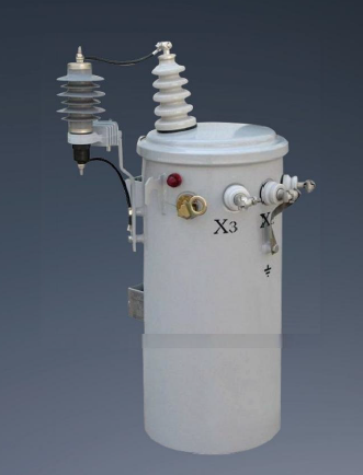
Data center tier topologies directly dictate equipment quantity and individual capacity. Redundancy ensures uptime during maintenance or unexpected hardware failures. You must align your electrical sizing with the facility tier rating.
Distributed redundancy (N+1) and system-plus-system (2N) architectures require different sizing approaches. An N+1 design spreads the load across multiple units. If one fails, the others absorb the remaining load. You size each unit to handle its normal share plus a fraction of the redundant load.
A 2N architecture provides complete duplication. Each unit must carry the full critical load independently during a failure scenario. You must size each unit to handle 100% of the facility demand. This approach maximizes reliability but significantly impacts initial infrastructure scale and footprint. In a 2N setup supporting a 5MW load, you need two separate 5MW utility feeds and two separate 5MW step-down units.
Redundant infrastructure carries heavy financial implications. Duplicating heavy electrical equipment doubles your initial capital outlay. It also requires more physical floor space and structural support. Concurrent maintainability demands dual power paths, further increasing complexity.
Oversizing for redundancy impacts the overall facility Power Usage Effectiveness (PUE). Redundant units often operate at lower utilization rates. Lower utilization means lower efficiency. You must balance the need for absolute fault tolerance against operational energy penalties.
Architecture Topology | Fault Tolerance Level | Typical Utilization Rate | Footprint Impact |
|---|---|---|---|
N (Base Capacity) | None (Single point of failure) | 80% - 90% | Minimal |
N+1 (Distributed) | High (Can survive one failure) | 60% - 75% | Moderate |
2N (System + System) | Maximum (Fully duplicated paths) | 40% - 50% | Double |
Modern data center hardware introduces severe power quality challenges. You must address these issues during the initial design phase to prevent catastrophic thermal failures.
IT equipment utilizes switched-mode power supplies. These devices draw current in short, abrupt pulses rather than smooth sine waves. This creates non-linear loads. Non-linear loads generate significant harmonic distortion within the electrical system. Variable frequency drives (VFDs) on cooling equipment also contribute heavily to this distortion.
Harmonic currents cause excessive skin-effect heating in standard windings. High-frequency currents travel on the outer edge of the conductors. This increases effective resistance and generates massive amounts of heat. Triplen harmonics (3rd, 9th, 15th) are particularly dangerous because they add together in the neutral conductor. Standard units will quickly overheat and fail under heavy harmonic loads. A standard neutral wire might carry 150% of the phase current due to these compounding triplen harmonics.
You must select the correct K-factor rating to mitigate thermal stress. The K-factor indicates a unit's ability to withstand harmonic heating safely.
K-4: Suitable for standard office environments with minimal non-linear loads.
K-13: The standard choice for most modern data centers and telecommunications facilities.
K-20: Reserved for extreme high-density computing environments with heavy VFD and UPS concentrations.
K-rated units feature distinct structural differences. They utilize double-sized neutral conductors to handle massive triplen harmonic currents. They also incorporate electrostatic shields to attenuate high-frequency noise. Selecting K-13 or K-20 depends entirely on your specific ratio of non-linear to linear loads. If your facility load is more than 75% non-linear, K-20 is the safest engineering choice.
Balancing initial capital expenditure against long-term operational expenditure is vital. Sustainability mandates also drive the push for better energy performance across the industry.
The Department of Energy (DOE) mandated strict efficiency standards in 2016. All distribution units manufactured for US deployment must meet these baselines. The standards aim to reduce grid-level energy waste across commercial sectors.
Meeting the baseline is often insufficient for hyperscale facilities. High-density enterprise data centers consume massive amounts of power. Even a fraction of a percent in efficiency loss translates to massive energy waste over time. You must look beyond the minimum legal requirements to achieve true operational excellence.
You must evaluate the financial impact of both no-load and load losses. No-load losses (core losses) occur continuously, regardless of the facility load. Load losses (coil losses) scale quadratically with the actual electrical demand.
Specifying a Low-Loss Power Transformer requires a larger upfront investment. However, premium magnetic core materials drastically reduce no-load losses. Amorphous metal cores perform significantly better than standard grain-oriented silicon steel. You can calculate the payback period by modeling energy costs over a 25-year lifecycle. The operational savings almost always justify the initial premium. A 2500 kVA unit operating at 99.5% efficiency instead of 99.0% saves hundreds of thousands of kilowatt-hours over its lifespan.
High efficiency provides secondary operational benefits. Electrical losses convert directly into heat. This heat rejects into the surrounding facility environment, creating a secondary problem.
A Low Line-Loss Power Transformer significantly reduces this thermal rejection. Lower heat output reduces the burden on your facility HVAC systems. Your cooling infrastructure works less, consuming less power. This compounding effect further improves your overall facility PUE. Every kilowatt of heat you prevent from entering the data hall saves additional energy that would otherwise power chillers and CRAH units.
Transformer Type | Core Material | Typical Efficiency | Heat Rejection | Best Application |
|---|---|---|---|---|
Standard DOE 2016 | Silicon Steel | Meets Baseline | Moderate to High | Standard commercial buildings |
Premium Silicon / Amorphous | Exceeds Baseline | Low | Hyperscale & High-Density Data Centers |
Interfacing with utility providers requires careful medium-voltage planning. You must manage high-voltage step-downs and integrate backup generation seamlessly to ensure reliability.
Most data centers receive medium voltage delivery. Standard ranges fall between 13.8 kV and 34.5 kV. Utility constraints directly dictate your primary winding specifications. You must match the utility delivery voltage precisely to ensure proper step-down ratios.
These units also interface with on-site medium-voltage generator plants. During utility outages, generators assume the load. The primary equipment must handle the transition smoothly. Phase synchronization and voltage regulation are critical during these transfer events. A delta primary and wye secondary configuration is standard to trap zero-sequence harmonic currents. This configuration prevents harmonic distortion from feeding back into the utility grid or the backup generators.
Transformer impedance (%Z) requires a critical balancing act. High impedance limits destructive fault currents during short circuits. However, high impedance also causes greater voltage drops under heavy load conditions.
Low impedance maintains tighter voltage regulation. Unfortunately, it allows massive fault currents to pass through to downstream equipment. The selected impedance dictates the sizing of downstream switchgear. You must coordinate impedance to ensure circuit breakers can safely interrupt potential faults without catastrophic arc flashes. A standard impedance of 5.75% offers a solid baseline, but high-density facilities might specify 8% to protect sensitive downstream switchboards.
Engineers must evaluate single-step versus dual-step voltage reduction. Single-step drops utility voltage directly to utilization voltage, such as 480V. Dual-step uses an intermediate voltage, like 4160V, for facility distribution before a final step-down near the IT load.
Liquid-filled units typically serve as outdoor substations for primary step-downs. They offer excellent cooling and high capacity. Dry-type units sit indoors closer to the IT loads. They eliminate fire risks associated with mineral oil but require robust indoor ventilation to manage ambient temperatures.
Navigating physical, logistical, and safety hurdles is just as important as the electrical math. Procurement challenges can derail an entire facility build if not managed proactively.
Macroeconomic supply chain constraints heavily impact heavy electrical equipment. Current market lead times stretch from 24 to 48 months. You cannot wait until the building shell is up to order electrical gear.
Early vendor engagement is absolutely critical. Standardize your specifications to avoid custom engineering delays. Secure production slots as early in the design phase as possible. Proactive procurement mitigates catastrophic project delays. Always mandate Factory Acceptance Testing (FAT) to verify performance before shipping.
Installing a multi-ton unit involves harsh physical realities. You must verify structural floor loading limits before placement. Rigging access paths must accommodate massive dimensions and extreme weights. Specialized transport, like lowboy trailers, is often required.
Clearance requirements dictate placement. You must leave adequate space for ventilation and routine maintenance. Crowding the equipment restricts airflow, leading to premature thermal degradation. Ensure crane lifts and rigging paths are clear of overhead obstructions. A 2500 kVA dry-type unit can weigh over 15,000 pounds, requiring heavy-duty structural steel support if placed on an upper floor.
Strict fire codes dictate indoor versus outdoor placement. Liquid-filled units require extensive fluid containment systems. Mineral oil poses a significant fire hazard. Many facilities now use less-flammable natural esters to mitigate this risk and comply with environmental regulations.
Indoor dry-type units must meet specific safety standards. FM Global approval is often required by insurance carriers. You must ensure all indoor placements comply with local fire marshal regulations and facility insurance mandates to avoid costly retrofits.
Engage a licensed electrical engineer to finalize comprehensive load studies and verify NEC continuous load derating calculations.
Model the 25-year operational energy costs to justify the capital expenditure for premium amorphous core materials.
Initiate vendor RFPs immediately during the schematic design phase to secure manufacturing slots and bypass 48-month lead times.
Coordinate with structural engineers to verify floor loading capacities and rigging paths for multi-ton equipment delivery.
A: You calculate kVA by aggregating all connected loads, including IT equipment, cooling infrastructure, and facility lighting. Apply realistic utilization factors to nameplate ratings. Finally, multiply continuous loads by 125% to ensure strict compliance with National Electrical Code (NEC) safety mandates.
A: A K-factor rating measures a unit's ability to withstand heat generated by non-linear loads. Data center IT equipment creates harmonic distortion. Ratings like K-13 or K-20 feature specialized windings and larger neutral conductors to prevent thermal failure under these harsh harmonic conditions.
A: Global demand for heavy electrical infrastructure has surged due to grid modernization, renewable energy projects, and hyperscale data center expansion. Material shortages for electrical steel and copper further constrain manufacturing. Consequently, lead times now frequently extend between 24 and 48 months.
A: Liquid-filled units use oil or natural esters for cooling. They offer higher capacities and typically sit outdoors in substations. Dry-type units use air for cooling. They are safer for indoor placement near IT loads because they eliminate the fire and spill risks associated with liquid coolants.
A: Impedance (%Z) restricts the flow of electrical current. Higher impedance limits destructive fault currents during a short circuit. This allows engineers to specify downstream switchgear and circuit breakers with lower interrupt ratings, safely protecting the facility infrastructure from catastrophic arc flashes.
A: Yes. Adding forced-air cooling fans accelerates heat dissipation. This allows the equipment to safely carry 25% to 33% more load than its base natural-cooling rating. Engineers use this temporary capacity bump to handle emergency redundancy scenarios without permanently oversizing the unit.

