


Views: 0 Author: Site Editor Publish Time: 2026-09-09 Origin: Site


Operating equipment across different regional power standards creates significant engineering hurdles. Global voltage disparities can ruin expensive electronics instantly. Integrating high-voltage infrastructure requires precise voltage reduction. The same applies when stepping down standard 220V utility power to 110V. Incorrect conversion setups frequently lead to catastrophic equipment failure. They can void expensive manufacturer warranties. They also create severe fire hazards in both residential and commercial facilities. We will demystify the internal mechanics of voltage reduction today. You will learn how to expose common point-of-failure risks that threaten your equipment. We also provide a strict evaluation framework. You can use this guide to specify the correct continuous-duty hardware for any demanding application.
A step down voltage converter primarily uses electromagnetic induction to safely reduce voltage, though cheaper electronic variants use solid-state switching (suitable only for simple heating elements).
Standard transformers reduce voltage but do not convert frequency (Hz)—a critical factor for motor-driven or timing-dependent equipment.
Safe capacity sizing requires a minimum 1.5x to 3x wattage buffer depending on the appliance's startup surge (inductive vs. resistive loads).
Industrial applications (e.g., utilizing a 10kV single phase step down transformer) require strict adherence to isolation, grounding, and thermal management standards not found in consumer-grade units.
Voltage reduction relies on specific physics principles to manipulate alternating current. Two distinct technologies dominate the market today. You must understand their differences to protect your connected equipment.
Traditional transformers utilize electromagnetic induction. They rely on dual copper coils wrapped securely around a heavy magnetic core. The primary coil receives the high-voltage input current. The secondary coil delivers the lower-voltage output. Voltage drops proportionally based on the exact ratio of turns between these two copper coils. A two-to-one winding ratio cuts the voltage exactly in half. This physical separation between coils provides natural electrical isolation. Such isolation significantly enhances safety for complex electronics. It prevents raw grid fluctuations from reaching sensitive circuit boards.
Solid-state devices use an entirely different engineering approach. They rely on cheap electronic circuitry rather than heavy copper coils. These circuits rapidly "chop" the AC sine wave into smaller segments. This aggressive switching reduces the average voltage delivered to your load. We issue a strong risk warning regarding this technology. Solid-state conversion often outputs a highly modified or square sine wave. This jagged waveform remains incredibly unsafe for delicate microprocessors. You should never use these devices for expensive audio equipment or motorized tools. They only serve simple, non-electronic heating elements safely.
Power delivery systems operate in different phases. A single phase voltage converter handles standard residential and light commercial loads. It isolates one alternating current cycle for consistent step-down delivery. You will often see them deployed in specific marine or off-grid solar applications. Three-phase systems handle massive industrial machinery. However, single-phase units remain the standard for localized, point-of-use equipment safety.
Voltage conversion hardware fails for predictable reasons. We constantly observe specific physical breakdowns when users deploy incorrect equipment. You must avoid these common electrical hazards.
Thermal Runaway and Overheating: Many systems fail due to poor thermal management. Continuous operation near maximum capacity traps excess internal heat. This rising temperature rapidly degrades internal coil insulation. Once the protective enamel melts, internal short circuits occur immediately. Fire risks escalate the moment this insulation fails.
The Frequency (Hz) Mismatch: Frequency mismatches present a subtle but critical danger. Standard conversion units only adjust voltage amplitude. They pass the electrical frequency through unchanged. Operating a 60Hz American motor on a European 50Hz supply causes severe mechanical stress. The motor runs 17 percent slower. It draws significantly more current to maintain torque. Overheating becomes inevitable under these conditions. Transformers simply cannot solve this frequency discrepancy.
Lack of True Grounding: Safety depends entirely on proper grounding paths. Cheap travel-grade converters often lack a true earth ground connection. This fatal design flaw creates direct shock hazards. Metal-chassis appliances become extremely dangerous if internal wire faults occur. The current will travel through the user rather than the ground wire.
Surge and Spike Vulnerability: Grid-level voltage spikes happen constantly in developing regions. Many budget converters lack built-in circuit breakers. They frequently omit internal fusing entirely. Without protective barrier components, transient grid energy passes directly through the unit. It strikes the connected load and destroys sensitive internal microchips.
Proper sizing prevents thermal breakdown and ensures continuous operation. Engineers rely on strict capacity guidelines known as the multiplier rule. Failing to follow these calculations usually results in burned-out hardware.
You must never match a converter’s maximum wattage exactly to your appliance’s running wattage. Equipment requires significant headroom to operate safely without generating excessive heat. We always recommend building a substantial buffer into your procurement specifications.
Resistive loads include standard lights, simple space heaters, and basic irons. These basic devices draw very steady power. They require a standard 1.2x to 1.5x safety margin. For example, a continuous 1000W load needs a 1500W rated step down voltage converter. This simple buffer prevents long-term thermal overload during extended daily usage.
Inductive loads demand much larger buffers. Motor-driven power tools, heavy heavy-duty compressors, and marine water pumps fall into this category. They experience massive inrush currents during their initial startup phase. This momentary electrical surge can easily triple the stated running wattage. Therefore, inductive equipment strictly requires a 2x to 3x safety margin. A 1000W electric motor demands a 3000W rated unit to start safely.
Procurement teams must carefully verify duty cycles before purchasing. Manufacturers often advertise absolute peak or short-term wattage ratings on the box. These numbers deceive average buyers. You must verify if the hardware carries a true "continuous 24/7" rating. Short-term peak ratings will fail under constant facility loads.
Table 1: Voltage Conversion Capacity Multiplier Chart
Load Type | Common Equipment Examples | Startup Surge Risk | Required Wattage Multiplier |
|---|---|---|---|
Pure Resistive | Incandescent lighting, simple heaters, irons | Low (Negligible inrush current) | 1.2x to 1.5x rating |
Standard Electronic | Laptops, televisions, basic medical devices | Low to Medium | 1.5x to 2.0x rating |
Light Inductive | Blenders, fans, small domestic appliances | Medium (Brief inrush surge) | 2.0x rating minimum |
Heavy Inductive | Air compressors, power saws, marine pumps | High (Massive startup current draw) | 2.5x to 3.0x rating |
Heavy-duty applications require specialized architectural designs. Industrial facilities cannot rely on consumer-grade technology. The demands of constant operation require superior materials and rigorous compliance standards.
Commercial hardware manufacturers generally choose between two magnetic core designs. Toroidal cores feature a continuous donut shape. They run remarkably cooler and produce significantly less audible hum. They operate more efficiently for continuous single-phase loads. Traditional square EI cores cost less to manufacture. However, EI cores generate more heat and vibration under heavy stress. We strongly advise specifying toroidal designs for quiet office or studio environments.
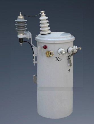
Utility networks operate on an entirely different scale. Regional power grids distribute electricity at incredibly dangerous voltage levels. Facilities must drop this medium-voltage grid power down to usable interior levels. A 10kV single phase step down transformer accomplishes this massive reduction efficiently. It translates raw utility distribution directly into stable 240V or 120V facility circuits.
Industrial scale equipment faces extreme compliance requirements. Engineers carefully evaluate oil-filled versus dry-type cooling methods. Oil immersion provides superior thermal stability for high-voltage exterior installations. Dry-type units work better indoors where fire codes restrict flammable liquids. Specifiers mandate specific NEMA enclosure ratings for weather resistance. Strict IEEE and IEC compliance ensures grid-level safety and long-term reliability.
Remote and specialized applications demand customized hardware solutions. Marine environments present unique challenges for electrical engineers. Yacht and cruiser shore power systems need specialized isolation units. These transformers prevent devastating galvanic corrosion on submerged metal boat hulls. Off-grid solar cabin setups also rely on robust isolation hardware. They manage variable AC generator inputs smoothly before delivering power to sensitive residential inverters.
Procurement teams need a structured approach to evaluate hardware. You must scrutinize internal components and safety marks meticulously. Follow these criteria to ensure safe facility operation.
Load Compatibility: You must verify equipment types first. Is your connected equipment purely resistive? Does it contain complex microprocessors or timing motors? This initial assessment dictates whether you can use a cheap solid-state converter or if you absolutely need a magnetic transformer.
Component Quality and Materials: Internal material quality dictates hardware longevity. Always look for units boasting 100 percent pure copper windings. Many budget brands utilize cheaper copper-clad aluminum (CCA) wire. Aluminum exhibits poor thermal stability. It becomes brittle and degrades faster under continuous heat. Pure copper guarantees better thermal conductivity and superior electrical efficiency.
Integrated Safety Features: Modern hardware must protect your facility actively. The unit must include high-quality resettable circuit breakers. Do not settle for one-time use glass fuses. Fuses fail unpredictably and tempt users to bypass them entirely. You also need integrated thermal protection switches. These essential sensors trigger an automatic shutoff if internal coil temperatures ever exceed safe operational limits.
Certifications and Compliance: Never compromise on verified safety standards. Shortlist only hardware bearing legitimate safety marks. These certifications must apply directly to your specific deployment region. Demand verifiable UL, CE, CSA, or RoHS labels. Inspect these labels closely, as counterfeit safety marks flood the online marketplace.
Safety in voltage conversion relies entirely on appropriate technology matching. You must pair the correct physical hardware with your specific electrical load. You also need rigorous capacity buffering and verified thermal management systems. Never guess your load requirements. Before procurement, audit the exact running wattage, frequency requirements, and startup surge profiles of the equipment you intend to power. We highly recommend you specify a single phase step down transformer for any critical application. Ensure your chosen hardware offers at least a 50 percent continuous capacity buffer above your maximum calculation. Implementing these strict guidelines guarantees uninterrupted daily operations and protects your expensive investments from electrical failure.
A: Transformers use magnetic induction (copper coils) and are safe for long-term use with all electronics. Converters use electronic circuits for short-term use, typically only safe for simple non-electronic heating devices (like basic hair dryers).
A: No. Standard step-down voltage transformers and converters only alter the voltage amplitude. They pass the electrical frequency through unchanged. Frequency conversion requires a specialized, much more expensive Variable Frequency Drive (VFD) or solid-state frequency converter.
A: Yes, provided it is a continuous-duty rated transformer properly sized for the load (with a healthy safety margin) and placed in a well-ventilated area. Consumer-grade electronic converters should never be left plugged in unattended.
A: A low hum is normal due to magnetostriction in the core. However, loud buzzing, excessive heat, or vibration indicates overload, loose internal laminations, or dirty incoming grid power (harmonics).

