


Views: 0 Author: Site Editor Publish Time: 2026-08-07 Origin: Site


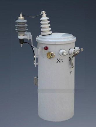
While the fundamental physics of voltage transformation remain static, the engineering tolerances dictating operational efficiency have evolved. Misunderstanding the internal mechanics of voltage stepping often leads engineering teams to over-specify capacity or under-prioritize core materials. This misalignment results in inflated capital expenditures and long-term operational inefficiencies. Understanding exactly how a single phase transformer works—from electromagnetic induction to thermal management—is the first step in evaluating and sourcing units that minimize lifecycle costs and meet stringent energy compliance standards. We will break down the core components, magnetic properties, and field application variables that dictate performance on the grid. By analyzing winding materials, core configurations, and cooling mediums, you can align equipment specifications directly with your site's load profile and environmental constraints.
Operational Foundation: As a static device with no moving parts, a single phase transformer operates on Faraday’s Law of Electromagnetic Induction, utilizing an alternating magnetic flux to transfer electrical energy between independent circuits without direct electrical connection.
Efficiency is Material-Dependent: The transition from a standard unit to a high efficiency single phase transformer relies heavily on core material selection (e.g., silicon steel vs. amorphous metal) to reduce hysteresis and eddy current losses.
Line Loss Mitigation: Specifying a low line loss single phase transformer requires precise alignment between the transformer’s impedance, winding materials, and the specific load profile of the distribution network.
Procurement Reality: Evaluating an energy saving single phase transformer demands a shift from initial purchase price analysis to a comprehensive lifecycle evaluation model that accounts for lifetime no-load and load losses.
To evaluate technical specifications effectively, you must first understand the baseline physics governing energy transfer. A transformer relies entirely on magnetic fields to move power from one circuit to another. It regulates voltage in static electrical devices without requiring moving parts. This simplicity makes the equipment highly reliable, but it also means internal material quality dictates overall performance. We see many field failures stem from a basic misunderstanding of how these magnetic fields interact with substandard core materials.
The operation begins when a single alternating current (AC) voltage waveform applies to the primary winding. Because the current alternates, it continuously changes direction and magnitude following a sine wave. This alternating current generates a time-varying magnetic field, known as magnetic flux, around the primary coil. According to Faraday’s Law of Electromagnetic Induction, a changing magnetic field induces an electromotive force (EMF) in any conductor exposed to it.
As the magnetic flux expands and collapses, it cuts across the secondary winding. This action induces a voltage in the secondary circuit. Power transfers seamlessly across the physical gap without any direct electrical connection. In field applications, this galvanic isolation provides a mandatory safety barrier between high-voltage distribution lines and low-voltage residential or commercial service drops.
Without a controlled path, magnetic flux would scatter into the surrounding air. Air has high magnetic reluctance, meaning it resists the flow of magnetic fields. To solve this, manufacturers wind the coils around a magnetic core. The core functions as a low-reluctance highway for the magnetic flux. It traps the magnetic field and channels it directly through the secondary winding.
Core permeability dictates the efficiency of this flux linkage. High-permeability materials ensure almost all the flux generated by the primary coil reaches the secondary coil. Poor core materials allow flux leakage, which directly degrades operational efficiency. When flux leaks, it can induce stray currents in the steel tank or clamping structures, leading to localized overheating and premature degradation of the insulating oil.
The actual voltage transformation depends on a simple mathematical relationship called the turns ratio. This ratio compares the number of wire turns in the primary winding to the number of turns in the secondary winding. If the secondary coil has fewer turns than the primary, the induced voltage decreases. This configuration acts as a step-down transformer, which is the most common application for utility distribution.
Conversely, if the secondary coil has more turns, the voltage increases, creating a step-up transformer. The power remains constant across both sides, minus minimal internal losses. Therefore, stepping down the voltage proportionally increases the available current. Field technicians use turns ratio testing (TTR) during commissioning to verify that the internal windings have not shorted and that the factory ratio matches the nameplate specifications.
Breaking down the physical architecture of the transformer helps assess build quality. Every component choice impacts thermal stability, mechanical strength, and application suitability. Engineers must evaluate these physical elements to match the equipment with specific site conditions.
Conductor material heavily influences performance and footprint. Manufacturers typically use copper or aluminum for the windings. Copper offers superior electrical conductivity. It allows for a smaller core and a more compact footprint. Copper also possesses high mechanical strength, which helps the coils withstand the violent physical forces generated during short-circuit faults.
Aluminum costs less and weighs significantly less than copper. However, aluminum requires larger cross-sectional areas to achieve the same conductivity. This increases the overall size of the unit. Aluminum also exhibits higher rates of thermal expansion, requiring specialized termination techniques to prevent loose connections over time.
Material Property | Copper Windings | Aluminum Windings |
|---|---|---|
Electrical Conductivity | Excellent (Standard reference) | Good (~61% of Copper) |
Tensile Strength | High (Better short-circuit withstand) | Lower (Requires robust bracing) |
Weight and Footprint | Heavier, compact design | Lighter, larger physical footprint |
Thermal Expansion | Low expansion rate | High expansion rate |
The physical arrangement of the windings and the core defines the structural type. Each configuration serves distinct operational environments.
In a core-type construction, the windings surround a considerable part of the core. This layout makes it easier to insulate the windings from the grounded core steel. Utilities typically specify core-type designs for high-voltage, low-power applications, such as pole-mounted distribution units. The exposed nature of the coils allows for better visual inspection and easier repair in specialized facilities.
In a shell-type construction, the core surrounds a considerable portion of the windings. This design provides superior mechanical protection and significantly lowers magnetic leakage. The surrounding steel acts as a shield. Shell-type designs are better suited for low-voltage, high-power applications where mechanical bracing against massive fault currents is a primary concern.
Internal faults usually stem from insulation breakdown or thermal degradation. Dielectric materials like kraft paper, enamel coatings, and cast resins separate the winding turns. These materials prevent short circuits within the coils. The degree of polymerization (DP) of the kraft paper serves as a direct indicator of the transformer's remaining lifespan. As heat and moisture degrade the paper, the DP value drops, making the insulation brittle.
Effective cooling mechanisms are mandatory to protect this insulation. Dry-type units use ambient air circulation for cooling. They require minimal maintenance and pose no spill risks, making them ideal for indoor commercial spaces. Liquid-filled units submerge the core and windings in dielectric fluids. Mineral oil remains the industry standard for outdoor distribution due to its excellent dielectric strength and cooling capacity. However, environmentally sensitive areas increasingly specify ester fluids. Ester fluids provide higher flash points for fire safety and rapid biodegradability in the event of a tank rupture.
Translating operational mechanics into measurable metrics reveals the true performance of the equipment. A high efficiency single phase transformer minimizes wasted energy across all load conditions. You must evaluate both core losses and copper losses to determine actual operational efficiency.
Core losses occur the moment you energize the unit, regardless of whether a load connects to the secondary side. These continuous losses stem from two primary phenomena: hysteresis and eddy currents. Hysteresis loss represents the energy required to constantly reverse the magnetic domains within the core material as the AC current alternates. Eddy current loss occurs when the changing magnetic field induces small, circulating currents within the core itself. These stray currents generate useless heat.
Engineers mitigate these losses by using laminated silicon steel. Instead of a solid block of metal, the core consists of hundreds of thin steel sheets, each coated with an insulating varnish. These thin laminations restrict the path of eddy currents, forcing them into smaller, less destructive loops. Furthermore, utilizing step-lap core joints improves flux distribution and reduces magnetic reluctance at the corners where the steel sheets meet.
Unlike core losses, copper losses vary directly with the connected load. These are I²R losses, caused by the natural electrical resistance of the winding conductors. As current (I) increases, the resistance (R) generates heat. Because this loss scales with the square of the current, overloading the unit causes an exponential spike in wasted energy and thermal stress.
Sizing the equipment to match the peak load profile prevents thermal degradation. Operating consistently near the unit's engineered peak efficiency point—usually between 50% and 70% of maximum capacity—keeps copper losses manageable. Advanced winding techniques also address the skin effect and proximity effect, where high-frequency currents crowd to the surface of the conductor, effectively increasing AC resistance.
Modern metallurgical advancements push efficiency boundaries further. Traditional silicon steel performs well, but amorphous metal cores offer superior energy retention. Amorphous metals feature a non-crystalline atomic structure, created by rapidly cooling molten metal before crystals can form.
This random arrangement allows magnetic domains to flip with almost zero friction. Consequently, amorphous cores reduce hysteresis losses by up to 70% compared to standard silicon steel. While these advanced materials require higher initial capital expenditure, the drastic reduction in continuous no-load losses pays dividends over a 20 to 30-year operational lifecycle. Manufacturers must handle amorphous steel carefully during production, as the material is inherently brittle, requiring specialized clamping structures to prevent core damage during transit.
Internal mechanics directly influence external network performance. This dynamic becomes especially apparent in rural or long-distance distribution networks. Specifying a low line loss single phase transformer ensures stable voltage delivery at the end of long conductor runs.
Percentage impedance (%Z) defines how much the voltage drops within the transformer under full load conditions. It represents the internal resistance to current flow. You must balance this metric carefully during the specification phase.
Low impedance provides excellent voltage regulation. The secondary voltage remains stable even as the load fluctuates, preventing lights from dimming when heavy motors start. However, low impedance allows massive fault currents to flow during a short circuit, potentially damaging downstream equipment. High impedance limits these destructive short-circuit currents but results in poorer voltage regulation. Engineers must calculate the optimal impedance to protect the network while maintaining steady voltage levels for end-users.
Accurate load profiling prevents severe operational inefficiencies. Under-loading a unit means it operates inefficiently because the constant core losses dominate the energy profile relative to the actual power delivered. You are essentially paying to magnetize a massive core for a tiny load.
Over-loading the unit triggers an exponential increase in copper losses. Sustained overloading pushes internal temperatures beyond the insulation's thermal rating. This degrades the dielectric paper, releases combustible gases into the oil, and drastically shortens the equipment's lifespan. Field technicians monitor these conditions using Dissolved Gas Analysis (DGA), drawing oil samples to detect trace gases like ethylene and hydrogen that indicate internal overheating.
These units serve distinct roles across modern power grids. Target applications include residential step-down service, commercial lighting circuits, and light industrial control panels. They also dominate rural single-wire earth return (SWER) systems. In SWER networks, a single high-voltage line covers vast distances, utilizing the earth as the return path. Running three-phase lines in these remote areas proves economically unviable.
However, you must identify the threshold where load demands necessitate upgrading to a three-phase unit. Pushing too much industrial motor load onto a single-phase network causes severe phase imbalance at the substation. Upgrading ensures operational stability and prevents localized grid stress.
Finalizing technical requirements requires a structured decision framework. Procurement teams must look beyond the initial capital outlay. You must evaluate compliance metrics, environmental risks, and long-term operational costs to secure a true energy saving single phase transformer.
A formulaic approach to evaluating equipment value is mandatory. You must calculate the initial capital expenditure alongside the projected cost of continuous no-load losses and variable load losses over the asset's lifespan. By assigning a specific financial value to every watt of wasted energy, you can accurately compare a standard unit against a premium, high-efficiency model. Often, the unit with the higher upfront cost delivers substantial financial savings over two decades of continuous operation.
Regional regulatory requirements dictate minimum efficiency baselines. In the United States, the Department of Energy (DOE) 2016 standards mandate strict efficiency levels for distribution equipment. In Europe, the EcoDesign directive enforces similar stringent requirements.
You must verify compliance by reviewing detailed manufacturer test reports. Ensure the vendor provides documentation for routine tests, type tests, and special tests. Routine tests include measuring winding resistance, checking the voltage ratio, and performing dielectric withstand tests. Advanced diagnostics like Sweep Frequency Response Analysis (SFRA) confirm mechanical integrity after shipping. These reports confirm that the delivered unit matches the promised efficiency metrics and thermal performance.
Deploying heavy electrical infrastructure carries inherent risks. You must identify and mitigate these challenges during the specification phase.
Environmental Hazards: Oil-filled units pose spill risks in ecologically sensitive areas or near waterways. Mitigate this by specifying biodegradable ester fluids or utilizing dry-type alternatives.
Harmonic Distortion: Non-linear loads, such as LED lighting and variable frequency drives, generate harmonic currents. These harmonics cause severe internal overheating. Mitigate this by evaluating the load profile and specifying a unit with an appropriate K-factor rating to handle the distorted waveforms.
Corrosion: Coastal or heavy industrial environments degrade steel enclosures rapidly. Mitigate this by requiring stainless steel tanks or specialized marine-grade powder coatings.
Moisture Ingress: Breathing transformers draw in ambient air as the oil cools and contracts. Mitigate moisture contamination by specifying high-quality silica gel breathers or sealed tank designs.
The fundamental working principle of a single phase transformer relies entirely on electromagnetic induction. However, the engineering execution separates legacy hardware from modern, highly efficient infrastructure. Procurement decisions must align the core type, winding material, and cooling method directly with the specific load profile and environmental constraints of the installation site. Haphazard specification leads to wasted energy and premature equipment failure.
Audit your current load profiles to identify baseline continuous loads and transient peaks before sizing new equipment.
Calculate acceptable efficiency thresholds based on local energy costs and regional regulatory requirements.
Request detailed loss data, including both no-load and load losses, from manufacturers before issuing a purchase order.
Evaluate the environmental constraints of your installation site to determine the safest cooling medium and enclosure material.
A: It operates on Faraday's law of electromagnetic induction. An alternating current in the primary winding creates a time-varying magnetic flux in the core. This alternating magnetic field cuts across the secondary winding, inducing a voltage. This allows energy transfer between circuits without any physical electrical connection.
A: Electromagnetic induction requires a changing magnetic field to induce voltage in the secondary winding. Alternating current (AC) naturally provides this continuously changing field. Direct current (DC) creates a static magnetic field, resulting in zero induction. Applying DC to a transformer acts as a short circuit and will burn out the primary winding.
A: Energy-saving models utilize premium materials like amorphous metal cores and highly refined copper windings. They feature optimized internal geometries and step-lap core joints. These specific engineering upgrades drastically reduce continuous hysteresis and eddy current losses, ensuring maximum electrical efficiency over the equipment's lifespan.
A: You reduce line loss by ensuring proper load sizing and minimizing internal impedance. Utilizing high-conductivity copper winding materials also helps. Most importantly, you must ensure the unit operates near its peak efficiency load point, typically between 50% and 70% of its maximum rated capacity.
A: In a core-type unit, the windings surround a large portion of the magnetic core, making it easier to insulate for high-voltage applications. In a shell-type unit, the core surrounds the windings. This provides better magnetic shielding and superior mechanical strength, making it ideal for low-voltage, high-power applications.
A: Core losses are constant no-load losses present whenever the unit is energized, caused by magnetizing the core. Copper losses are variable load losses caused by the electrical resistance of the windings. Copper losses scale with the square of the electrical current drawn. Both reduce overall operational efficiency.
A: While it will induce a voltage on the corresponding secondary phase, it causes severe magnetic flux imbalances within the core. This drastically reduces the transformer's rated capacity and causes localized overheating. It is generally not recommended for standard operations without specialized phase-conversion engineering.

