


Views: 0 Author: Site Editor Publish Time: 2026-09-22 Origin: Site


In industrial facilities and power distribution networks, mismatched voltage causes catastrophic equipment failure. It also leads to severe energy loss and prolonged operational downtime. You cannot run high-demand machinery on standard utility feeds without proper conditioning. A step up transformer bridges this exact gap between low-voltage generation and high-voltage transmission requirements. It takes a lower incoming voltage and scales it up for efficient long-distance power grids. It also provides crucial boosts for heavy-duty localized applications. Proper voltage scaling reduces line losses and prevents massive thermal damage to your electrical infrastructure. Before specifying a unit for a critical facility, engineers and procurement teams must understand the underlying mechanics. You also need to know its operational limitations and specific evaluation criteria. We will explore how these systems function, compare them to step down units, and review common procurement pitfalls. This ensures you install a reliable solution rather than a dangerous liability.
A step up transformer increases voltage from the primary to the secondary winding while proportionally decreasing current, maintaining overall power (minus efficiency losses).
Applications range from large-scale power generation to specific heavy-machinery operation, requiring precise kVA and insulation specifications.
Attempting to "reverse feed" a step down transformer instead of buying a dedicated step up unit introduces severe compliance risks, grounding issues, and inrush current hazards.
A step up transformer operates on the core principle of electromagnetic induction. We owe this foundational concept to Faraday's Law of Induction. You pass alternating current (AC) into the primary coil. This current builds a rapidly collapsing and expanding magnetic field inside the core. The magnetic flux travels through the core material and intersects the secondary coil. This intersection induces a new voltage in the secondary wire. We rely heavily on this process because it transfers massive amounts of energy efficiently. It requires zero moving parts. This minimizes mechanical wear and ensures long-term operational stability.
The entire induction process depends entirely on the turns ratio. The primary coil features fewer wire turns. It receives the low-voltage input directly from your power source. The secondary coil contains many more turns. It outputs the newly created high voltage. The mathematical relationship remains strictly proportional.
Power, measured in Watts, remains theoretically constant across both sides of the unit. Because energy cannot appear from nowhere, the unit must trade current for voltage. As voltage steps up significantly, current steps down proportionally. If you double the voltage, you cut the current in half. This voltage-to-current trade-off allows power companies to transmit energy across hundreds of miles using thinner cables.
Manufacturers do not use solid steel blocks for the magnetic core. A solid steel block would generate massive heat during operation. Instead, engineers build these cores using thin, laminated silicon steel sheets. These specialized insulated sheets minimize eddy currents. They also reduce magnetic hysteresis losses. This precise material engineering directly improves the unit's operational efficiency. It keeps internal temperatures stable during peak load times. Poor core construction leads to excessive heating and premature insulation degradation.
People often confuse step up and step down units. They share similar physical enclosures but differ entirely inside. Engineers design these two types differently to handle specific electrical stresses.
Winding thickness dictates current capacity. High-current coils require very thick copper or aluminum conductors to prevent melting. Low-current coils use much thinner wires. Therefore, a step up unit features thick wire on the primary side and thin wire on the secondary side. A step down unit reverses this exact configuration.
Insulation placement also shifts drastically. High-voltage secondary coils demand extreme insulation layering. This thick insulation prevents dangerous electrical arcing between the closely packed turns. Step down units place their heaviest insulation on the primary receiving side.
Comparison Matrix: Operational and Structural Specifications
Feature | Step Up Configuration | Step Down Configuration |
|---|---|---|
Voltage Flow | Low to High (Primary < Secondary) | High to Low (Primary > Secondary) |
Conductor Sizing | Thick primary / Thin secondary | Thin primary / Thick secondary |
Current Flow | Decreases at output | Increases at output |
Primary Use Cases | Grid transmission, Renewable generation | Facility distribution, End-user machinery |
Facilities must specify the exact directional flow of power during procurement. You cannot simply guess the setup or rely on generic inventory. Buying the wrong unit causes mismatched impedance. Mismatched impedance leads to massive overheating and catastrophic failure. You must define your electrical flow clearly early in the design phase. This guarantees grid stability and protects downstream equipment.
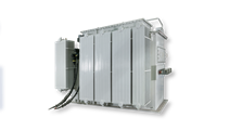
We see these units deployed across various critical sectors. They solve unique voltage challenges in renewable generation, manufacturing, and commercial infrastructure.
Solar farms and wind turbines generate low voltage internally. They typically produce outputs between 400V and 690V. You cannot push this low voltage across miles of utility lines. The resistance would burn off most of the energy as heat. We solve this by installing a dedicated power step up transformer directly at the generation site. It boosts the power to grid-level voltages like 11kV or 33kV. This high voltage allows the green energy to travel efficiently over long distances to reach urban substations.
Consider a localized manufacturing scenario. A facility receives standard 208V or 240V utility feeds. The company purchases specialized heavy European machinery requiring a strict 480V input. Rewiring the entire facility from the utility pole costs a fortune. Instead, the facility installs a localized unit right on the factory floor. This acts as a perfect step up transformer example. It isolates the voltage boost only to the specific machine line. It prevents the need for a total facility electrical overhaul.
Hospitals and large data centers rely heavily on backup generators. These generators often output lower voltages than the main facility switchgear expects. Engineers integrate localized boosting units to match the systems. They match the generator output to the main switchgear voltage perfectly. This ensures smooth, uninterrupted operation during utility outages. It protects sensitive servers and life-saving medical equipment from brownouts.
Many procurement teams believe transformers operate perfectly in both directions. This dangerous myth persists across many industries. They assume you can simply wire a step down unit backwards. They do this to save money or beat long manufacturing lead times.
The myth suggests that because induction works in both directions, any unit functions bidirectionally. While physically possible to wire, it ignores critical engineering safeguards. Engineers design step down units specifically for high-to-low power flow.
We strongly advise against reverse feeding. It introduces severe risks to your infrastructure and personnel.
Inrush Current: Reversing the feed targets the low-voltage winding first. This specific winding sits closer to the core and has very low impedance. Energizing it backwards creates massive magnetic saturation. This draws massive inrush currents. These currents trip main breakers instantly and cause constant nuisance faults.
Voltage Drop and Compensation: Step down units feature compensated windings. Manufacturers add extra turns to the secondary side. This compensates for natural voltage drops under heavy load. Running the unit backward compounds this drop. You receive a dangerously low output voltage when your machinery runs.
Compliance and Grounding: The National Electrical Code (NEC) strictly governs equipment usage. Reverse-fed transformers often lose their designated neutral reference. You can no longer ground the system properly. This creates massive grounding hazards. It violates electrical safety codes and voids equipment warranties immediately.
You might physically wire a unit backwards in a desperate pinch. However, doing so creates an absolute liability for permanent installations. Critical-path industrial applications require dedicated, purpose-built equipment. Never compromise facility safety to save a few weeks on delivery. Always purchase equipment engineered specifically for your power flow direction.
Proper evaluation prevents costly installation errors. You must look beyond basic voltage ratings. Evaluate loads, environmental factors, and efficiency metrics thoroughly.
Your procurement process begins with accurate load calculation. You must calculate the exact kVA required by your machinery. Do not under-size the unit to save money. Undersized units run too hot, burn their insulation, and fail prematurely. Do not vastly over-size the unit either. Massive oversizing creates unnecessary core losses. It wastes energy continuously, even when your machinery sits idle.
You must choose between liquid-filled and dry-type units. Evaluate your installation location carefully.
Dry-Type: Indoor setups usually require dry-type transformers. They use cast resin or epoxy. They reduce fire risks significantly inside commercial buildings.
Liquid-Filled: Outdoor utility pads benefit from rugged liquid-filled designs. Mineral oil or synthetic fluids provide superior cooling for massive loads.
Always specify premium insulation classes for a high voltage step up transformer. Proper insulation prevents internal arcing. It guarantees long-term reliability under severe electrical stress.
Always verify regional efficiency mandates. In the United States, ensure the unit meets DOE 2016 efficiency compliance. Other regions have equivalent strict environmental standards. You must request factory test reports prior to final purchase. Look closely at three specific metrics:
Certified impedance values to ensure grid compatibility.
Documented load losses at full capacity.
No-load losses (core losses) during standby operation.
Smart procurement moves far beyond the initial purchase price. Evaluate manufacturers based on realistic production lead times. Scrutinize their warranty terms. Ask about customized tap configurations. A good unit features primary tap changers. Custom taps help you handle local utility voltage fluctuations efficiently. This keeps your machinery running smoothly despite external grid instability.
A step up unit is never a simple, generic commodity. It serves as a highly engineered electrical component. Facility safety, grid stability, and operational efficiency all depend directly on its quality. You must match the transformer's engineering to your exact industrial requirements.
Avoid the common temptation to reverse-feed inappropriate step down equipment. Base your procurement strictly on calculated kVA loads and strict efficiency mandates. Prioritize safety and long-term performance above short-term convenience.
Always consult with an experienced electrical engineer before making your final decision. Reach out to your technical sales team today. We will gladly review your single-line electrical diagrams. We can help you specify the exact transformer required to make your specific project a success.
A: When a transformer increases voltage, it must decrease current proportionally. This trade-off maintains power equilibrium based on the law of conservation of energy. If the voltage doubles, the current cuts in half. This reduces heat and allows for efficient long-distance power transmission over much thinner utility wires.
A: No, a transformer cannot increase total power. The conservation of energy states that power in equals power out. In reality, actual output power slightly decreases. Core heating, eddy currents, and magnetic resistance cause minor efficiency losses during the electromagnetic induction process.
A: You calculate the required load using a standard formula. For a 3-phase system, multiply Volts by Amps, then multiply by 1.732. Divide that number by 1000 to find your baseline kVA. Always add a 20 to 25 percent safety margin to prevent future overloading.
A: Reverse feeding targets the low-voltage windings first. These windings have lower impedance and resistance. When energized, they draw a massive initial surge called inrush current. This surge easily exceeds standard breaker limits, causing immediate tripping and potential long-term damage to your electrical infrastructure.

