


Views: 0 Author: Site Editor Publish Time: 2026-08-05 Origin: Site


Stepping down high-voltage power is a non-negotiable requirement for residential grids, light commercial facilities, and rural infrastructure. In these specific locations, running three-phase power lines is structurally unfeasible and economically impractical. You need a reliable method to convert transmission voltages into usable localized power. This is exactly where a single phase transformer proves its value. It provides a localized, efficient, and reliable power supply directly to end-users.
Selecting the right unit presents a significant engineering and procurement challenge. You must balance load capacity, environmental constraints, and lifecycle durability while minimizing no-load losses. A poorly specified unit leads to thermal degradation, excessive energy waste, and premature failure. This guide covers the exact technical specifications you need to make an informed decision. We move from fundamental magnetic induction principles to advanced procurement criteria, evaluating specific models, component breakdowns, and modern high-efficiency variants.
Application Specificity: A single phase transformer is the standard for localized power distribution, specifically in rural networks, residential step-down applications, and specific industrial control circuits.
Cooling and Insulation Matter: The choice between dry-type and a single phase oil immersed transformer dictates installation location (indoor vs. outdoor), maintenance schedules, and thermal overload capacity.
Efficiency Standards Drive ROI: Modern designs, such as the D11-M(R) single phase transformer, utilize wound core technology to drastically reduce no-load losses and operational noise.
Lifecycle Evaluation: Procurement must evaluate beyond initial capital expenditure, factoring in copper/core losses, expected lifespan (typically 20-30 years), winding materials, and routine maintenance requirements.
Understanding how this equipment operates requires looking at basic physics. The device relies entirely on electromagnetic induction. It transfers electrical energy between two isolated circuits using a fluctuating magnetic field. There are no moving parts. This static nature contributes to its high reliability and long operational lifespan in the field.
Faraday’s Law of Induction governs this process. When alternating current flows through the primary winding, it creates a time-varying magnetic field. This magnetic field travels through the highly permeable core. As the magnetic flux cuts through the secondary winding, it induces an alternating voltage. The frequency remains constant between the primary and secondary sides. Only the voltage and current levels change. This principle allows safe and efficient power transfer across different voltage levels. In field applications, this means taking a 7,200V distribution line and safely dropping it to 120/240V for residential use without direct electrical contact between the high and low voltage sides.
Manufacturers build these units using two primary architectural styles. Each offers distinct mechanical and electrical characteristics that dictate their use in specific environments.
Core-Type Construction: The windings surround the magnetic core. The core forms a simple rectangular loop. This design provides excellent natural cooling for the windings because they are exposed to the surrounding oil or air. It is easier to dismantle for repair in a maintenance shop. However, it may experience slightly higher magnetic flux leakage compared to shell types.
Shell-Type Construction: The magnetic core surrounds the windings. The core features a central limb where both primary and secondary coils are wound. This structure provides better mechanical protection for the coils. It significantly reduces magnetic flux leakage, making it highly efficient. It is highly robust but much more complex to repair if a winding fails, often requiring a complete rebuild.
Feature | Core-Type Construction | Shell-Type Construction |
|---|---|---|
Winding Placement | Surrounds the core | Surrounded by the core |
Cooling Efficiency | High (windings exposed) | Moderate (windings enclosed) |
Mechanical Protection | Lower | Higher |
Repairability | Easier to dismantle | Complex and time-consuming |
Flux Leakage | Slightly higher | Very low |
The exact output voltage depends on the turns ratio. This is the ratio of wire turns on the primary coil to the turns on the secondary coil. The formula is straightforward: Np/Ns = Vp/Vs. Np represents primary turns, and Ns represents secondary turns. Vp is primary voltage, and Vs is secondary voltage. If the primary coil has 1000 turns and the secondary has 100 turns, the ratio is 10:1. A 10,000V input will step down to 1,000V. This precise mathematical relationship ensures end-user equipment receives the exact voltage required for safe operation. Field engineers use this ratio to verify nameplate data during commissioning, ensuring the tap changer is set to the correct position for the local grid voltage.
A transformer is only as reliable as its internal components. High-quality materials prevent thermal breakdown and minimize energy losses. Let us examine the critical parts that make up these units and how they perform under heavy field loads.
The core provides the pathway for magnetic flux. Modern units use cold-rolled grain-oriented (CRGO) silicon steel. This material is highly permeable. It offers very low reluctance to the magnetic field. The silicon content increases electrical resistivity, which minimizes eddy current losses. The grain-oriented structure aligns the metal crystals in the direction of the flux. This significantly reduces hysteresis losses. The result is a highly efficient core that stays cooler under continuous operation. Substandard core steel leads to excessive heating and high no-load losses, draining efficiency over the equipment's lifespan.
The primary and secondary coils carry the electrical current. Engineers must choose between copper and aluminum for these windings. Both materials have specific trade-offs that impact the physical size and thermal performance of the unit.
Copper Windings: Copper offers superior electrical conductivity. It allows for a smaller physical footprint. It possesses high mechanical strength to withstand short-circuit forces. Copper is heavier and carries a higher initial material cost, but its durability in high-stress environments is unmatched.
Aluminum Windings: Aluminum is highly cost-effective. It is significantly lighter than copper. To achieve the same conductivity, aluminum windings require a larger cross-sectional area. This increases the overall size of the unit. Aluminum also has a higher coefficient of thermal expansion, requiring specialized termination techniques like Belleville washers to prevent loose connections over time.
Bushings safely route high-voltage connections through the grounded metal tank. They prevent electrical tracking and short circuits. Outdoor units typically use porcelain bushings. Porcelain offers excellent weather resistance and durability against UV degradation. Polymer bushings are becoming more common in modern installations. They are lighter, highly resistant to vandalism, and offer superior hydrophobic properties in wet environments. The internal conductor connects to the windings, while the external terminal connects to the utility grid. A cracked bushing is a primary cause of moisture ingress and subsequent dielectric failure.
The outer tank protects the internal components from environmental damage. In a single phase oil immersed transformer, the tank also holds the dielectric fluid. Heat dissipation is a major operational factor. As the core and windings generate heat, the oil absorbs it. The hot oil rises and circulates through corrugated fins or external radiators. These fins maximize the surface area exposed to the ambient air. The air cools the oil, which then sinks back to the bottom of the tank. This natural convection cycle prevents thermal overload. Heavy-duty tanks are fabricated from thick carbon steel and coated with weather-resistant polyurethane or epoxy paints to prevent rust in coastal or industrial environments.
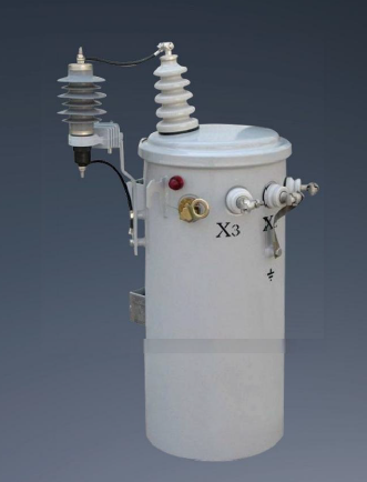
You must match the transformer type to the specific installation environment. Different configurations serve distinct operational needs. Selecting the wrong category leads to safety violations, code failures, and premature equipment breakdown.
This unit serves as the final stage of the utility grid. It steps down medium voltage to the low voltage required by homes and small businesses. You will typically see two main physical configurations in the field.
Pole-Mounted Units: These are lightweight and space-saving. They sit high on utility poles, keeping high-voltage lines away from pedestrians and traffic. They are the standard for rural electrification and older residential neighborhoods where overhead lines are common.
Pad-Mounted Units: These sit on concrete pads on the ground. They are used for underground distribution networks. They feature secure, tamper-proof enclosures to protect the public from live electrical parts. They are heavily used in modern suburban developments and commercial parks.
A standard single phase distribution transformer typically ranges from 5 kVA up to 167 kVA. The exact rating depends on the density of the load it serves and the expected peak demand of the connected properties.
These units use a liquid coolant for both dielectric insulation and thermal dissipation. Traditionally, manufacturers use highly refined mineral oil. Modern environmentally sensitive installations may use synthetic esters or natural seed oils. These alternative fluids have higher flash points and biodegrade rapidly if spilled, making them ideal for installations near waterways or protected lands.
Oil-immersed units offer significant operational advantages. They handle higher load capacities effectively. The liquid cooling provides superior thermal management during peak demand spikes. They offer excellent outdoor weather resistance. The sealed tank protects the core and windings from moisture and dust. This results in a longer lifespan under heavy electrical stress compared to air-cooled alternatives.
Dry-type units do not use liquid coolants. They rely on air circulation for heat dissipation. The windings are often encased in cast resin or treated with vacuum pressure impregnation (VPI). This protects them from environmental moisture and mechanical stress.
You must specify dry-type units when fire safety is the primary concern. They are mandatory for indoor commercial buildings, hospitals, schools, and underground vaults. They are also common in marine applications. Because they lack cooling oil, they are generally larger and more expensive than oil-immersed units of the same kVA rating. They also have lower tolerance for severe overloads, requiring careful load management.
Procuring the right equipment requires rigorous technical evaluation. You cannot simply buy based on the lowest initial price. You must analyze load demands, efficiency metrics, and regulatory compliance to ensure long-term reliability.
Sizing the unit correctly is your first step. You must calculate the peak load demand and compare it to the continuous load. Add up the wattage of all connected devices. Convert this total to kVA.
Under-sizing is dangerous. It leads to severe thermal degradation. The insulation will break down, causing a catastrophic short circuit. It also causes unacceptable voltage drops at the end-user equipment, leading to motor stalling and electronics failure. Over-sizing is wasteful. It results in excessive no-load losses. You pay for energy you do not use. It also wastes capital expenditure. Aim for a unit where your average continuous load sits between 50% and 70% of the rated kVA.
You must differentiate between the two primary types of energy loss to evaluate true operational efficiency.
No-Load (Core) Losses: These occur the moment you energize the unit. They happen regardless of the connected load. They are caused by hysteresis and eddy currents in the steel core. You pay for these losses 24 hours a day, 365 days a year.
Load (Copper) Losses: These vary with the load current. They are caused by the electrical resistance of the winding materials. They peak when the unit operates at maximum capacity.
Evaluate the efficiency curve provided by the manufacturer. Match the peak efficiency point to your facility's average load factor. This ensures maximum energy savings over the unit's lifespan.
Your equipment must meet strict regulatory standards. These standards govern temperature rise limits, dielectric strength, and energy efficiency mandates. In the United States, look for compliance with DOE 2016 efficiency standards. In Europe, Tier 2 eco-design directives apply. Ensure the unit meets relevant IEEE, ANSI, or IEC specifications. Non-compliant equipment may fail electrical inspections, delay project commissioning, and incur heavy fines from regulatory bodies.
Do not compromise on supplier quality. Verify that the manufacturer holds ISO 9001 and ISO 14001 certifications. Review their warranty terms carefully. Most importantly, demand comprehensive Factory Acceptance Test (FAT) reports prior to shipment. The FAT proves the unit meets all specified electrical and mechanical criteria before it leaves the factory floor. It should include routine tests like winding resistance measurement, voltage ratio verification, and dielectric withstand tests.
Evaluation Metric | Oil-Immersed Transformer | Dry-Type Transformer |
|---|---|---|
Cooling Medium | Mineral Oil or Synthetic Esters | Ambient Air (Natural or Forced) |
Installation Location | Primarily Outdoor | Strictly Indoor / Fire-Sensitive Areas |
Overload Capacity | High (Excellent thermal mass) | Low to Moderate |
Maintenance Needs | Fluid sampling, leak checks | Vacuuming dust, visual inspection |
Fire Risk | Higher (if using standard mineral oil) | Very Low (Self-extinguishing materials) |
When efficiency and reliability are paramount, modern engineering offers advanced solutions. The D11-M(R) single phase transformer represents a significant leap in distribution technology. It is typically a fully sealed, oil-immersed unit featuring a highly optimized wound core.
The "M" usually denotes a fully sealed tank structure. This eliminates contact between the insulating oil and the outside atmosphere. It prevents moisture ingress and oil oxidation, which are the primary causes of dielectric breakdown. The "R" signifies the wound core technology. Instead of stacking flat sheets of steel, the manufacturer winds a continuous strip of CRGO silicon steel to form the core. This manufacturing technique requires specialized winding machines but produces a vastly superior magnetic circuit.
Traditional stacked cores have tiny air gaps at the joints where the steel plates meet. These air gaps disrupt the magnetic flux. They increase reluctance and cause energy loss. The continuous strip construction eliminates these air gaps entirely.
This design yields measurable improvements. Excitation current drops significantly. No-load losses are drastically reduced. The continuous magnetic pathway also minimizes harmonic distortion, providing cleaner power to sensitive downstream electronics. For utility companies managing thousands of units, these incremental efficiency gains translate into massive energy savings across the grid.
Facility managers experience immediate practical benefits. The elimination of air gaps significantly reduces acoustic noise. The characteristic transformer hum is barely audible, making these units ideal for dense residential neighborhoods. The wound core structure also enhances short-circuit withstand capability. The circular or oval windings distribute mechanical stress more evenly during fault conditions, preventing coil deformation. Finally, the optimized magnetic pathways allow for a smaller physical footprint. This makes installation easier in tight spaces or on crowded utility poles where weight and wind load are major concerns.
Proper procurement is only half the battle. You must install and maintain the equipment correctly. Neglecting lifecycle management leads to catastrophic failures, extended power outages, and severe safety hazards for operating personnel.
Site preparation is critical. For pole-mounted units, verify the structural integrity of the pole. Ensure it can handle the static weight and wind loads. Grounding is absolutely essential. You must establish a low-resistance path to earth, typically driving copper-clad ground rods deep into the soil. Proper grounding prevents transient overvoltage damage and protects personnel from step-and-touch potentials during a fault. Ensure all connections are torqued to the manufacturer's exact specifications to prevent hot spots.
You must protect the unit from grid anomalies and localized faults. Integrate primary cut-out fuses to isolate the unit during a catastrophic internal failure. Install heavy-duty surge and lightning arresters on the primary side. These divert high-voltage spikes safely to ground before they can puncture the winding insulation. Use secondary circuit breakers to protect the windings from prolonged downstream overloads caused by end-user equipment failures.
Implement a realistic and strict maintenance schedule. Do not wait for a failure to inspect the unit. Proactive maintenance extends the equipment's life by decades.
Visual Inspections: Check for bushing leaks, tank corrosion, and cracked porcelain regularly. Look for oil stains on the concrete pad or the pole.
Dielectric Testing: Perform dielectric breakdown voltage testing on the oil to ensure it retains its insulating properties. Moisture contamination will drastically lower the breakdown voltage.
Dissolved Gas Analysis (DGA): This is the most critical test. DGA detects trace gases in the oil caused by arcing or overheating. It provides early warning of impending internal failure, allowing you to schedule a replacement before an unplanned outage occurs.
Modern electrical loads are rarely linear. Computers, LED lighting, and variable frequency drives generate harmonic distortion. Harmonics cause excessive heating in standard windings. If you anticipate high harmonic loads, you must specify a K-factor rating. A K-factor rated unit features oversized neutral conductors and specialized winding techniques to handle harmonic heating safely.
For sealed units, monitor internal pressure. Ensure the pressure relief valves function correctly. These valves vent excess pressure if the oil boils during a severe fault, preventing the tank from rupturing. Check temperature indicators to verify the unit operates within its designed thermal limits during peak summer loads.
Specifying the correct equipment requires strict attention to detail. You must align the unit's cooling method, core technology, winding material, and kVA rating with the exact environmental and load profile of the site. There is no universal solution. Every installation demands a tailored approach based on field conditions and electrical demand.
Use clear shortlisting logic. Choose a standard distribution model for typical utility grid step-down applications. Opt for an oil-immersed unit for harsh outdoor environments requiring high durability and thermal tolerance. Specify advanced models like the D11-M(R) when long-term energy efficiency, low operational noise, and minimal maintenance are your top priorities.
Take the following actions to secure the right equipment for your next project:
Conduct a comprehensive load profile analysis to determine your exact kVA requirements and peak demand periods.
Review local utility compliance standards and environmental regulations regarding oil containment and energy efficiency.
Request detailed factory acceptance test (FAT) reports and maintenance projections from shortlisted manufacturers.
Establish a clear grounding and surge protection strategy before finalizing the installation site.
A: A single-phase unit operates on a single alternating current cycle. It is smaller, has simpler wiring, and is used primarily for residential and light commercial step-down applications. A three-phase unit handles three overlapping AC cycles. It is larger, more complex, and designed for heavy industrial loads and major grid transmission.
A: They are the backbone of localized power delivery. You will find them heavily deployed in rural electrification projects, residential neighborhoods, and light commercial zones. They step down the medium voltage from utility lines to the standard 120/240V required by everyday appliances and lighting systems.
A: When properly specified and maintained, these units typically last 20 to 30 years. Longevity depends heavily on load management and oil quality. Routine maintenance, specifically keeping the oil free of moisture and monitoring for dissolved gases, prevents insulation breakdown and extends the operational life significantly.
A: This nomenclature describes specific design features. The "11" refers to the efficiency class. The "M" indicates a fully sealed tank design that prevents oil oxidation. The "R" signifies wound core technology, which uses a continuous steel strip to eliminate air gaps, thereby reducing no-load losses and operational noise.
A: Use the basic formula: kVA = (Volts × Amps) / 1000. Calculate the total continuous amperage required by your connected load, multiply it by the required secondary voltage, and divide by 1000. Always apply a 20-25% safety margin to accommodate future expansion and prevent thermal overloading.
A: Routine maintenance includes visual checks for oil leaks, tank corrosion, and cracked bushings. For oil-immersed units, you must perform annual oil sampling for Dissolved Gas Analysis (DGA) and dielectric strength testing. Infrared thermography is also recommended to detect loose external connections before they fail.
A: Neither is universally better; it depends on your priorities. Copper offers better electrical conductivity, higher mechanical strength, and a smaller physical footprint. Aluminum provides a lower initial material cost and lighter overall weight. Both perform reliably for decades if the manufacturer engineers the terminations and cooling systems correctly.

