


Views: 0 Author: Site Editor Publish Time: 2026-08-24 Origin: Site


Scaling heavy-commercial operations requires robust power distribution. Standard single-phase systems simply cannot support massive industrial loads safely or efficiently. Facility operators quickly reach a ceiling where power upgrades become an absolute necessity. A 3 phase transformer is a critical infrastructure component designed specifically for this exact purpose. It steps up or steps down electrical voltage in a three-phase power system. The device utilizes three interconnected coils mounted securely on a single magnetic core to manage heavy currents. This guide transitions directly from basic definitions to practical, real-world application. We will help facility managers, mechanical engineers, and procurement teams evaluate essential configurations. You will learn how to assess technical specifications accurately and mitigate serious installation risks. By the end, you can confidently standardize your procurement shortlist and ensure continuous operational success.
Efficiency at Scale: A 3 phase transformer delivers continuous, non-pulsating power, significantly reducing copper wiring costs and electrical losses compared to single-phase setups.
Application-Specific Configurations: Choosing between Star (Wye) and Delta connections dictates load balancing capabilities and grounding safety.
Total Cost of Ownership (TCO): Upfront pricing is secondary to evaluating core efficiency (load vs. no-load losses), cooling requirements (dry vs. liquid), and footprint constraints.
Risk Mitigation: Proper KVA sizing, phase converter matching (if retrofitting), and compliance with IEEE/IEC standards are non-negotiable for site safety and equipment longevity.
Standardizing power delivery remains a massive challenge for growing industrial plants. Heavy machinery, massive HVAC systems, and continuous manufacturing lines demand incredibly stable power. You cannot rely on erratic energy delivery when operating sensitive automated equipment. Upgrading your infrastructure prevents dangerous voltage drops across your facility. It also helps you avoid excessive utility penalties caused by poor power factors. Managers need a reliable solution delivering massive energy without constantly tripping breakers.
This specialized equipment operates on three separate alternating currents simultaneously. These currents peak at different, staggered intervals during the electrical cycle. They sit exactly 120 degrees apart from one another. Think of it like a three-cylinder engine providing a continuous, overlapping power stroke. When one current drops from its peak, another immediately rises to take its place. The magnetic flux generated by these three windings perfectly balances out within the central core.
This elegant design ensures constant, uninterrupted power flow. It completely avoids the zero-voltage points inherent in standard single-phase electrical cycles. Because the power never drops to zero, your industrial motors run noticeably smoother. They experience far less mechanical vibration during daily operation. Consequently, expensive machinery lasts longer and requires fewer maintenance interventions. Furthermore, running a three-phase network consumes far less conductor material. You save significant money on copper wiring overhead while achieving superior energy transmission.
When exactly do you need to upgrade your facility? Single-phase systems become a major liability once you pass specific electrical thresholds. Operations exceeding 1000 watts of continuous draw or driving heavy motor loads require immediate infrastructure upgrades. Pushing single-phase networks too hard causes severe overheating. It triggers frequent breaker tripping and creates unsafe working conditions. Heavy industrial motors actually require three-phase power just to generate sufficient starting torque.
A single three phase power transformer offers remarkable physical and mechanical advantages over legacy setups. It requires significantly less iron core material to function. It weighs substantially less and occupies a much smaller physical footprint. You save premium floor space compared to banking three separate single-phase transformers together. A single enclosure requires less sheet metal and fewer exterior cooling fins. This consolidated design lowers your initial shipping costs and simplifies the rigging process during installation.
You also consolidate potential failure points across your electrical grid. One integrated unit heavily streamlines your annual maintenance schedules. Technicians only need to inspect one housing, one set of bushings, and one cooling system. However, this consolidation requires you to demand rigorous baseline manufacturing quality. If one internal phase winding fails, it typically disables the entire integrated unit. You cannot simply swap out one third of the machine. Therefore, upfront investment in high-quality insulation and superior core materials becomes absolutely critical for operational reliability.
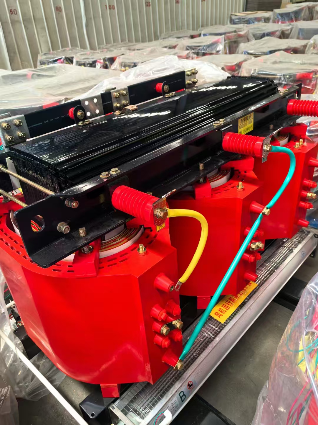
Selecting the correct internal winding topology directly impacts your operational safety. You must match the internal coil connections precisely to your specific load profiles. Engineers typically configure both the primary and secondary windings in either a Delta or Star (Wye) arrangement.
We summarize the most common winding topologies in the decision matrix below.
Winding Topology Decision Matrix
Configuration Strategy | Best Operational Application | Key Engineering Benefit |
|---|---|---|
Star-Star (Wye-Wye) | Facilities with mixed loads requiring a neutral wire. | Safely powers single-phase lighting alongside heavy three-phase motors. |
Delta-Delta | Harsh industrial environments demanding maximum reliability. | Can temporarily operate at 57.7% capacity if one phase fails (Open Delta). |
Delta-Star (Wye) | The absolute industry standard for commercial step-down applications. | Stabilizes transmission lines while feeding safe distribution networks. |
Many older facilities completely lack native three-phase grid access. You might need to retrofit older buildings situated in rural or legacy commercial zones. Upgrading utility lines directly often proves prohibitively expensive. In these scenarios, engineers often match 220V configurations to rotary phase converters.
This strategic bridging connects legacy infrastructure to modern machinery demands. The rotary converter artificially generates the missing third leg of power. The transformer then steps that power to the exact voltage required by your CNC machines or industrial pumps. You must ensure the transformer sizing perfectly accommodates the slight phase imbalances introduced by the converter. Proper impedance matching prevents dangerous harmonic distortion from damaging your sensitive equipment.
You must evaluate multiple technical metrics before purchasing a three phase distribution transformer. Relying purely on the initial purchase price inevitably leads to poor procurement decisions.
First, you must clearly differentiate between core losses and copper losses. Core losses, also known as no-load losses, happen constantly. They occur the moment you energize the equipment, regardless of whether machinery is running. Copper losses, or load losses, scale up directly alongside your facility's power demands. Investing in high-efficiency core materials requires larger upfront capital. However, it guarantees strong operational returns over the equipment's lifespan through reduced daily energy waste.
Next, you need to match the cooling mechanism directly to your operating environment.
Air-Cooled (Dry Type): These units are significantly safer for indoor commercial use. They pose a much lower fire risk because they utilize ambient air and solid resins for insulation. However, they remain highly sensitive to environmental contaminants. Heavy dust, airborne chemicals, or poor ventilation quickly degrades their performance.
Liquid-Filled (Oil Type): These units provide vastly superior cooling for high-capacity applications. They routinely handle massive 132kV outdoor substation loads. The mineral or synthetic oil easily dissipates extreme heat. However, choosing this route requires you to install strict spill-containment infrastructure to prevent environmental contamination.
Finally, you must rigorously verify local regulatory compliance. Your equipment must meet strict NEMA enclosure ratings. It should align perfectly with IEEE C57 standards or equivalent IEC global codes. Proper certification ensures immediate insurance compliance. It guarantees operational safety and protects your workforce from catastrophic arc flash incidents.
Proper capacity planning dictates the success of your electrical rollout. Undersizing your 3 phase transformer causes severe overheating and guarantees premature insulation failure. Oversizing creates unnecessary capital expenditure and subjects you to excessive, parasitic no-load losses for decades. Follow a proven industry rule of thumb. Calculate your maximum continuous load, then size your unit for 120 to 125 percent of that number. This specific buffer safely accommodates future expansion and temporary motor-starting surges.
You must prepare your physical site carefully before delivery. Structural engineers need to evaluate concrete pad weight limits. Liquid-filled variants represent immense physical density. The foundation must support tons of steel and oil without cracking or shifting. You must also implement heavy-duty vibration isolation pads. Transformers emit a constant, low-frequency hum due to magnetostriction. Noise mitigation becomes absolutely critical in populated commercial zones or office-adjacent utility rooms.
Look far beyond raw specifications when shortlisting potential vendors. Scrutinize their warranty terms and replacement part availability. Will they ship replacement bushings overnight, or will you wait weeks? Demand complete transparency during Factory Acceptance Testing (FAT). You should receive detailed reports on impulse testing and heat run trials before the unit leaves their facility. Reliable post-installation support distinguishes true engineering partners from mere hardware suppliers.
Specifying this critical electrical infrastructure represents a major, long-term operational commitment. Your final procurement decision directly impacts daily facility uptime and utility overhead for decades to come. Taking shortcuts during the evaluation phase always results in costly downstream failures.
Always match the internal winding configuration strictly to your exact load type. Prioritize long-term operational efficiency and material quality over the cheapest initial hardware cost. Rigorously audit your physical site constraints, cooling requirements, and regulatory obligations before making a final selection.
Take decisive action today to secure your facility's power backbone. Request a custom load analysis from your trusted engineering team to map your true power requirements. Download a detailed technical specification sheet to compare cooling methodologies and loss metrics. Contact an engineering sales team to validate your sizing calculations and ensure a flawless future installation.
A: Yes, but you need specialized conversion equipment. You must install a rotary phase converter or a Variable Frequency Drive (VFD). These devices artificially generate the missing electrical phases. However, they possess strict capacity limitations. VFDs work well for individual motors but struggle with mixed facility loads. Rotary converters handle larger networks but introduce minor efficiency losses.
A: This specialized equipment handles minor, highly specific voltage corrections. It steps up or steps down the electrical supply by roughly 5 to 20 percent. Facilities use them to match localized utility grids to specific equipment ratings. If your grid supplies 208V but your imported machinery requires 230V, a buck-boost unit safely bridges this gap.
A: These robust units typically last between 25 and 30 years. Some well-maintained systems operate efficiently for over 40 years. Lifespan heavily depends on rigorous load management and heat control. You must perform regular preventative maintenance. Activities like routine oil sampling and thermal imaging detect early wear before catastrophic failure occurs.
A: Base your decision on installation location and total capacity. Choose dry-type units for indoor commercial spaces. They minimize fire risks but dislike heavy dust and poor ventilation. Select oil-filled units for outdoor, high-capacity industrial applications. Oil offers vastly superior cooling for massive electrical loads but requires dedicated concrete spill-containment infrastructure.

