


Views: 0 Author: Site Editor Publish Time: 2026-08-17 Origin: Site


Incorrect transformer sizing carries severe operational and financial consequences. Undersizing leads to dangerous thermal degradation, frequent breaker trips, and premature equipment failure. Oversizing wastes capital upfront and generates continuous efficiency losses throughout the unit's lifespan. Facility engineers and procurement teams face a complex challenge. You must match electrical load requirements with the exact kVA rating while accounting for motor inrush currents, phase balancing, and harsh environmental variables. A methodical, evidence-based framework removes the guesswork from specifying a single phase transformer. This guide covers exact mathematical formulas, material specification trade-offs, and implementation risk mitigation. You will learn how to calculate base loads, apply necessary safety margins, and select the right core and winding materials for optimal performance.
Base Calculation: The fundamental sizing formula for a single phase transformer is kVA = (Load Amps × Load Volts) / 1,000, but this is only the baseline.
Safety Margins: Industry standard practice requires a minimum 20% capacity buffer to accommodate future expansion and prevent overheating during peak loads.
Material Impact: Specification choices—such as selecting a silicon steel core or copper windings—directly dictate the transformer’s lifecycle efficiency, core losses, and thermal management capabilities.
Environmental Constraints: Operating conditions dictate insulation and cooling requirements, making the choice between dry-type and oil-insulated units a critical decision-stage factor.
Successful sizing goes beyond simply meeting current load demands. You must ensure voltage stability, regulatory compliance, and thermal reliability over a 20 to 30-year lifespan. Proper sizing prevents voltage drops that can damage sensitive electronics and ensures the magnetic core operates within its optimal flux density range. Field failures rarely happen because of manufacturing defects; they happen because the unit specified does not match the physical realities of the installation site.
Start by auditing the connected load to determine total wattage or volt-amperes (VA). You need accurate data to build a reliable specification. Relying on estimates or outdated facility drawings often leads to critical specification errors. When auditing a site, you must physically inspect the equipment.
List every piece of equipment connected to the dedicated circuit.
Record the voltage and amperage requirements directly from the equipment nameplates. Do not rely on user manuals, as field modifications are common.
Verify the primary supply voltage available at the installation site using a true RMS multimeter. Utility voltages fluctuate, and a nominal 480V supply might actually meter at 495V.
Confirm the secondary load voltage required by your machinery.
Match the frequency to your regional grid and equipment specifications. A 50Hz transformer will overheat if applied to a 60Hz load without proper derating.
Account for the power factor (PF) if equipment is rated in Watts. Calculate VA by dividing Watts by the PF. Resistive loads like heaters have a PF of 1.0, while inductive loads like motors often sit around 0.8.
The standard calculation is straightforward: kVA = (V × I) / 1000. Here, V represents load volts and I represents load amps. This differs significantly from three-phase sizing. Do not use the 1.732 multiplier. Applying three-phase formulas to single-phase systems causes massive calculation errors, resulting in severely undersized or oversized equipment.
Consider a practical field example. You need to power a remote lighting panel and a few small pumps. The total load requires 240V and draws 150 Amps. The calculation is (240 × 150) / 1000 = 36 kVA. Transformers use apparent power (kVA) rather than real power (kW) because they must handle both resistive and reactive loads. The kVA rating accounts for the total current flowing through the windings, regardless of the power factor of the connected devices.
Load Type | Voltage (V) | Current (A) | Base kVA Calculation | Standard Size Available |
|---|---|---|---|---|
Security Lighting | 120 | 40 | 4.8 kVA | 5 kVA |
HVAC Blower | 240 | 65 | 15.6 kVA | 25 kVA |
Pump Station | 480 | 110 | 52.8 kVA | 75 kVA |
Define the application direction early in the design phase. A step-up configuration increases voltage for efficient long-distance transmission, minimizing line losses across large industrial campuses. A step-down configuration reduces voltage for safe end-user equipment operation, such as dropping 480V down to 120/240V split-phase for standard wall outlets.
Specify primary and secondary tap configurations. Standard options include +/- 2.5% or 5% taps. These taps allow electricians to fine-tune voltage regulation in the field. If the utility supply voltage runs consistently high, adjusting the taps ensures the secondary voltage remains stable. This protects sensitive loads from overvoltage conditions and prevents motors from stalling due to undervoltage during peak grid demand hours.
Different load characteristics alter the baseline kVA calculation. You must evaluate these operational factors to finalize a robust specification that withstands daily industrial demands. A mathematically perfect calculation fails if it ignores how the equipment actually runs in the real world.
A continuous load operates at maximum current for three hours or more. Lighting systems, data center servers, and continuous manufacturing processes are common examples. Intermittent loads operate for shorter durations with cooling periods in between, such as a breakroom microwave or a sump pump.
Regional standards, such as the National Electrical Code (NEC) Article 450, require sizing continuous loads at 125% of the maximum current. This prevents thermal buildup inside the enclosure and protects the insulation system from premature degradation. Failing to apply this 125% rule to continuous loads guarantees overheating. The internal varnish will bake, become brittle, and eventually cause a phase-to-phase short circuit.
Inductive loads like motors and compressors generate high starting currents. This inrush current can be six to ten times the normal running current. If you only size for the running kVA, the voltage will dip severely during equipment startup. This voltage sag causes contactors to chatter, computers to reboot, and other motors on the same circuit to stall.
Calculate the maximum starting kVA alongside the running kVA. Check the motor nameplate for the NEMA design code letter. This letter helps determine the locked rotor kVA per horsepower. Size the unit to handle this temporary spike without dropping the secondary voltage below the minimum operating threshold of your critical equipment.
NEMA Code Letter | Locked Rotor kVA per HP | Impact on Sizing |
|---|---|---|
F | 5.0 - 5.59 | Moderate inrush, standard buffer usually sufficient. |
G | 5.6 - 6.29 | Average inrush, requires careful voltage drop calculation. |
J | 7.1 - 7.99 | High inrush, often requires upsizing the transformer. |
L | 9.0 - 9.99 | Severe inrush, mandatory capacity increase required. |
Standard engineering practice dictates adding a 20% to 25% safety margin to the total calculated load. This buffer serves multiple critical functions in field operations. It is not a guess; it is a calculated risk mitigation strategy.
Accommodates future equipment additions without requiring an expensive transformer replacement.
Extends equipment lifespan by reducing continuous thermal stress on the windings and core.
Provides headroom for unexpected harmonic loads generated by non-linear devices like variable frequency drives.
Ensures the unit operates closer to its peak efficiency point, which typically sits between 50% and 80% of full load capacity.
Internal construction materials dictate upfront costs and operating efficiency. Your material choices directly impact long-term reliability and thermal management capabilities. Do not default to the cheapest option without evaluating the lifecycle expenses associated with energy losses and maintenance.
Conductor material is a primary specification decision. Copper offers superior electrical conductivity and higher tensile strength compared to aluminum. Because copper is a better conductor, it requires less cross-sectional area to carry the same amount of current. Aluminum requires larger conductors, which increases the overall physical footprint of the equipment.
Specifying a copper winding single phase transformer provides distinct lifecycle advantages. It significantly lowers I²R losses, which reduces internal heat generation. The higher tensile strength withstands the severe mechanical stresses of short circuits far better than aluminum. Aluminum windings are prone to cold flow at termination points, requiring specialized lugs and regular torque maintenance to prevent loose connections and arcing. Copper windings allow for a more compact core and coil assembly, making them ideal for space-constrained electrical rooms or crowded utility poles.
The magnetic core plays a vital role in overall efficiency. The universal EMF equation illustrates how flux density dictates core sizing. The material used for the core determines how effectively it conducts the magnetic field. Poor core materials waste massive amounts of electricity as heat, even when no load is connected to the secondary side.
Specifying a silicon steel core single phase transformer minimizes hysteresis and eddy current losses. High-grade grain-oriented silicon steel aligns the crystalline structure of the metal with the magnetic flux path. This alignment drastically reduces the energy required to magnetize and demagnetize the core during each alternating current cycle. Manufacturers use thin laminations coated with insulating varnish to further restrict eddy currents. While high-grade silicon steel carries a higher initial procurement cost, the long-term energy savings from reduced no-load losses easily justify the investment.
Material Choice | Primary Advantage | Best Application Scenario |
|---|---|---|
Copper Windings | Lower I²R losses, compact footprint, high short-circuit strength | Space-constrained areas, high-efficiency needs, heavy industrial loads |
Aluminum Windings | Lower initial material cost, lighter overall weight | Budget-conscious projects with ample installation space |
Silicon Steel Core | Reduced hysteresis and eddy current losses, stable flux density | Continuous operation, strict energy-saving mandates |
Amorphous Metal Core | Ultra-low no-load losses, excellent light-load efficiency | Renewable energy grids, high-efficiency utility distribution |
External factors can cause a mathematically correctly sized unit to fail in the field. You must account for the operating environment to ensure the insulation system survives. Heat and moisture are the primary enemies of electrical insulation.
Dry-type units use ambient air for cooling and are common indoors. They rely on ventilation grilles and natural convection. Liquid-filled units use specialized dielectric fluids for superior heat dissipation and insulation, making them far more robust for severe environments.
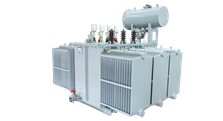
Many industrial, outdoor, or high-voltage applications mandate an oil insulated single phase transformer. Oil provides exceptional dielectric strength and thermal dissipation, protecting the internal components from harsh weather, moisture ingress, and heavy continuous loads. The fluid circulates through the windings, carrying heat away to the external radiators. However, oil insulation requires strict maintenance protocols. You must perform regular dissolved gas analysis (DGA) to detect internal faults early. You also need to implement environmental compliance measures, such as secondary spill containment pits, to prevent soil contamination in the event of a tank rupture.
Standard ratings assume a maximum ambient temperature of 40°C (104°F) and an average of 30°C over a 24-hour period. If ambient temperatures exceed 40°C, you must apply capacity derating. The unit cannot dissipate heat effectively in hotter environments, requiring a larger kVA rating to handle the same load without exceeding its maximum temperature rise limits. For example, a unit rated for a 65°C rise will quickly exceed its insulation limits if placed in a 50°C boiler room.
Altitude also heavily impacts cooling. Thinner air at high elevations reduces convective heat transfer. If you install the equipment above 3,300 feet (1,000 meters), you must apply altitude correction factors. A common rule is derating the capacity by 0.3% for every 330 feet above the 3,300-foot threshold. Failure to derate for altitude leads to rapid overheating, insulation breakdown, and eventual short circuits. If you are installing a unit in Denver, Colorado (elevation 5,280 feet), you must calculate this derating factor before finalizing the purchase order.
Field experience reveals several common pitfalls in the procurement and specification process. Avoid these engineering errors to ensure system reliability and safety. Relying on guesswork instead of hard math always leads to operational failures.
The myth that bigger is always better causes significant engineering errors. Severe oversizing leads to poor voltage regulation under light loads. It also increases core losses, which occur continuously regardless of the connected load. You waste capital expenditure on a larger unit, heavier cabling, and oversized protective breakers.
Furthermore, an oversized unit has a lower percentage impedance relative to your actual load. This lower impedance allows massively higher short-circuit fault currents to flow during a fault condition. This can easily exceed the interrupting rating of your downstream circuit breakers. If a fault occurs, the breaker will fail to clear the arc, creating a severe fire and safety hazard that can destroy the entire electrical panel.
Undersizing presents severe physical realities. Pushing a unit beyond its rated capacity generates excessive internal heat. This heat accelerates insulation degradation, cutting the operational lifespan from decades to mere years. The rule of thumb states that for every 10°C the operating temperature exceeds the insulation rating, the life expectancy of the equipment is cut in half. You will smell the varnish burning long before the unit finally fails.
Undersizing also causes severe voltage drops during peak demand. This undervoltage leads to equipment malfunction, frequent breaker trips, motor stalling, and catastrophic failure risks. Always match the capacity closely to the calculated load plus the standard buffer. Never assume a transformer can handle a continuous overload just because it survives the initial startup.
Compile a comprehensive list of your voltage, amperage, and frequency requirements directly from equipment nameplates.
Identify any continuous loads or high-inrush motor equipment on the circuit to calculate maximum peak demand accurately.
Determine the maximum ambient temperature and exact altitude of your installation site to apply necessary derating factors.
Select core and winding materials based on long-term efficiency and the physical constraints of your installation environment.
Consult with a certified electrical engineer to review your calculations, verify fault current limits, and finalize the design before procurement.
A: Use the formula: (Volts × Amps) / 1000. For example, a 240V load drawing 100A requires 24 kVA. Always add a recommended 20% safety margin to this baseline. Note that this differs from three-phase calculations, which require an additional 1.732 multiplier.
A: kW represents real power that performs actual work. kVA represents apparent power, which is the total power supplied to the circuit. Transformers are rated in kVA because they must handle both the real power and the reactive power required by inductive loads, determined by the power factor.
A: Copper offers superior thermal conductivity and lower electrical resistance. This results in less heat generation and lower I²R losses. Copper's higher tensile strength also withstands short-circuit forces better, and it allows for a smaller, more compact equipment footprint compared to aluminum.
A: Oil insulation is typically required for outdoor utility applications, high-voltage transmission, and environments needing aggressive cooling. The liquid provides superior dielectric strength and thermal dissipation compared to dry-type air cooling, making it ideal for harsh industrial conditions.
A: Yes. High-grade grain-oriented silicon steel aligns the magnetic flux path, which significantly reduces no-load losses. It minimizes magnetic hysteresis and eddy currents, optimizing flux density and ensuring the unit wastes less energy as heat during continuous operation.
A: Motor starting loads can be six to ten times the running current. You must consult the motor's NEMA code letter to determine the exact locked rotor kVA. Calculate this spike to ensure the transformer can handle the temporary surge without severe voltage drops.
A: Yes. You must apply derating factors if the ambient temperature exceeds 40°C (104°F) or if the installation altitude is above 3,300 feet (1,000 meters). Thinner air and higher ambient heat reduce cooling efficiency, requiring a larger kVA rating to prevent overheating.

