


Views: 0 Author: Site Editor Publish Time: 2026-08-13 Origin: Site


Incorrect transformer sizing introduces severe operational risks to any facility. Undersizing leads directly to accelerated thermal degradation. Insulation breaks down prematurely, risking catastrophic failure and unplanned downtime. Conversely, oversizing wastes capital expenditure. It consumes excessive floor space and forces the unit to operate inefficiently, driving up no-load core losses over decades of operation.
Facility engineers and procurement teams face a strict balancing act. You must meet immediate load requirements while planning for future scalability. You also have to navigate environmental constraints and strict energy efficiency mandates like DOE 2016 or EcoDesign. Basic kVA calculations are no longer sufficient. Specifying a dry power transformer requires a deep evaluation of primary and secondary voltage matching, environmental de-rating factors, and facility harmonic profiles.
Load Profiling is Foundational: Accurate sizing requires distinguishing between continuous, non-continuous, and peak motor-starting loads, applying appropriate demand and diversity factors.
Voltage and Tap Configurations Matter: Matching primary and secondary voltages while accounting for supply fluctuations via tap settings is critical for stable power distribution.
Environmental De-Rating is Non-Negotiable: Ambient temperature, altitude, and enclosure ventilation directly reduce effective capacity and must be calculated prior to final specification.
Harmonics Dictate Design: Non-linear loads require K-factor rated transformers to manage excess heat generation without premature insulation failure.
Transformer sizing directly dictates the thermal dynamics of the equipment. Heat generation scales with the square of the applied electrical load due to I²R losses in the windings. Dry type units rely entirely on ambient air for cooling, making the insulation class the main defense against this heat. A standard Class 220°C insulation system withstands significant internal temperatures. Running consistently above the rated capacity destroys this chemical protection. Industry standards dictate that insulation life halves for every 10°C you operate over the thermal limit. An undersized unit running just 20°C over its limit will reduce a 20-year expected lifespan down to 5 years.
Insulation Class | Maximum Hot Spot Temperature | Typical Temperature Rise | Common Application |
|---|---|---|---|
Class 150°C | 150°C | 80°C | Older legacy systems, specialized low-temp environments. |
Class 180°C | 180°C | 115°C | Standard commercial distribution, light industrial. |
Class 220°C | 220°C | 150°C | Heavy industrial, high-ambient environments, modern standard. |
Efficiency curves present another sizing challenge. Transformers do not operate at flat efficiency rates across their load spectrum. They typically hit peak efficiency between 35% and 50% of their maximum load rating. Drastically oversizing a unit forces it to operate at the bottom of this curve. The core continuously draws power just to stay magnetized, regardless of the actual facility load. These no-load losses accumulate into massive operational penalties.
Inrush current also scales directly with transformer size. Energizing a larger core draws a massive transient current spike, often 10 to 12 times the full load amp (FLA) rating. Oversizing increases this inrush multiplier. You will need heavier upstream switchgear to handle the initial surge without nuisance tripping. This complicates breaker coordination and forces unnecessary upgrades to primary protection devices.
Accurate sizing requires a granular inventory of all connected electrical loads. You must categorize these loads by type and operational profile. Group your lighting circuits, HVAC systems, heavy motor loads, and sensitive IT electronics. Lighting and IT equipment generally represent continuous loads, meaning they operate for three hours or more without interruption. HVAC and motors cycle on and off, creating non-continuous profiles. Documenting these distinctions prevents gross overestimation of the baseline power draw.
Define the exact supply voltage from the utility and the required load voltage for the facility. A common industrial application involves stepping down a 480V primary feed to a 208Y/120V three-phase secondary. Voltage matching is rarely perfect in the field. Utility feeds fluctuate based on grid demand. Specify primary tap settings, such as FCAN (Full Capacity Above Normal) and FCBN (Full Capacity Below Normal). These taps allow you to adjust the winding ratio in the field. A standard configuration includes two 2.5% FCAN and two 2.5% FCBN taps, providing a ±5% adjustment range to compensate for localized overvoltage or undervoltage.
Equipment nameplates list power in Amps, Volts, or Kilowatts (kW). Convert all these values into Kilovolt-Amperes (kVA) to establish a uniform sizing metric.
For single-phase loads, multiply Volts by Amps and divide by 1,000.
For three-phase loads, multiply Volts by Amps, multiply by 1.732, and divide by 1,000.
When converting kW to kVA, divide the kW rating by the Power Factor (PF).
A motor with a 0.8 PF will require significantly more kVA than a purely resistive heater of the same kW rating. For example, a 100kW motor with a 0.8 PF requires 125 kVA of transformer capacity. Failing to account for power factor results in immediate undersizing.
Adding up every nameplate rating yields a massively inflated number. Facilities never run every piece of equipment simultaneously at full load. Apply demand and diversity factors to find the realistic peak draw. Demand Factor represents the maximum demand of a system divided by the total connected load. It applies to individual equipment groups. Diversity Factor represents the sum of individual maximum demands divided by the maximum demand of the entire system. It accounts for the time-staggered nature of different loads.
Facility Type | Typical Lighting Demand Factor | Typical Receptacle Demand Factor |
|---|---|---|
Hospitals | 40% for loads over 50kVA | 50% for loads over 10kVA |
Hotels and Motels | 40% for loads over 20kVA | 50% for loads over 10kVA |
Warehouses | 50% for loads over 12.5kVA | 50% for loads over 10kVA |
Motors draw significantly more current during startup than during normal operation. Account for Locked Rotor Amps (LRA), which can be six to eight times the running current. Large motor startups cause transient voltage drops across the distribution system. If the transformer lacks the capacity to handle this sudden surge, the secondary voltage will sag. This sag can cause sensitive electronics to reboot or magnetic contactors to drop out. Size the unit to maintain acceptable voltage regulation during the largest anticipated motor start.
Once you calculate the diversified peak load, add a safety margin. A standard 20% to 25% buffer is optimal. This margin accommodates unforeseen operational changes and minor facility expansions. It keeps the transformer operating near its peak efficiency curve. Pushing the safety margin to 50% crosses into oversizing territory, increasing core losses and wasting floor space.
Sizing the transformer dictates the sizing of the upstream and downstream overcurrent protection devices. The National Electrical Code (NEC) Article 450 provides strict maximum rating percentages for primary breakers based on the transformer's primary current and impedance. If you oversize the transformer, the primary breaker size increases. This larger breaker may fail to coordinate with the downstream secondary breakers. In a fault condition, a lack of coordination causes the main primary breaker to trip before the localized secondary breaker clears the fault, plunging the entire facility into darkness. Accurate sizing ensures tight breaker coordination and isolates faults to specific branch circuits.
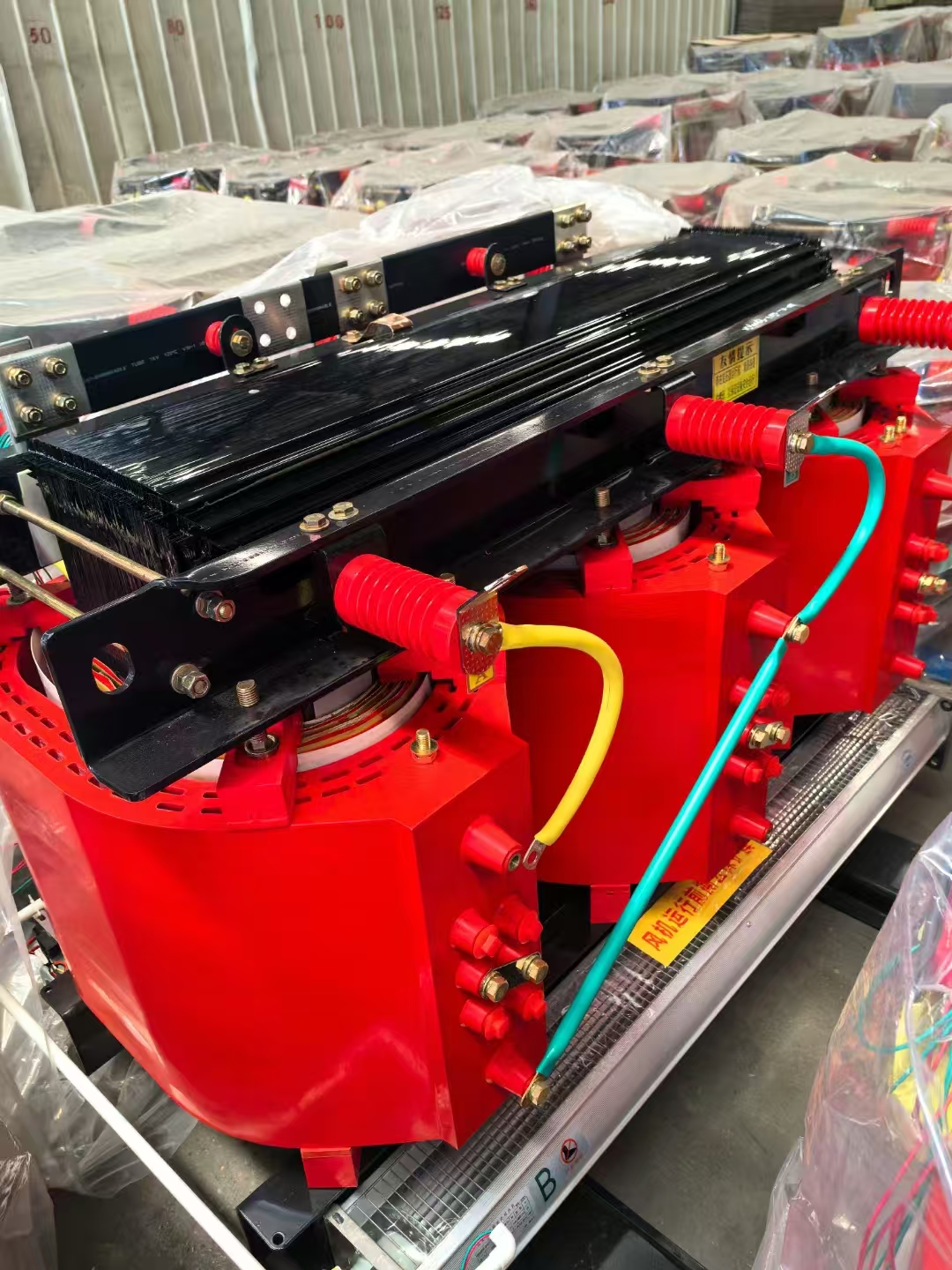
Air density decreases as altitude increases. Thinner air absorbs and carries away less heat from the transformer coils. Standard transformer ratings assume an installation altitude below 1,000 meters (3,300 feet). If you install the unit above this elevation, you must de-rate its capacity. The standard formula requires a 0.3% reduction in kVA capacity for every 100 meters above the 1,000-meter baseline.
Installation Altitude | Cooling De-Rating Multiplier | Dielectric Strength De-Rating |
|---|---|---|
1,000 meters (Base) | 1.00 | 1.00 |
1,500 meters | 0.985 | 0.95 |
2,000 meters | 0.970 | 0.90 |
3,000 meters | 0.940 | 0.80 |
Failure to apply this de-rating leads to rapid overheating in mountainous installations. A 1000 kVA unit installed at 2,000 meters will lose 3% of its effective capacity, dropping to 970 kVA. The dielectric strength of the air also decreases, requiring larger electrical clearances between phases.
Transformer nameplates assume specific ambient temperature baselines. This is typically a 30°C average over 24 hours, with a maximum peak of 40°C. Installing a unit in a sweltering electrical room or a hot industrial plant changes the thermal math. Higher ambient environments leave less thermal headroom for the insulation. You must either specify a larger kVA rating to lower the internal heat generation or upgrade to forced-air cooling. Adding cooling fans (AF rating) can temporarily boost a transformer's capacity by up to 33% during peak temperature events.
Modern facilities are packed with non-linear loads. Variable Frequency Drives (VFDs), LED lighting drivers, and IT server power supplies draw current in abrupt pulses. These pulses distort the sine wave, creating harmonic frequencies. Harmonics generate severe eddy current losses and excessive heat in standard transformer windings. Evaluate the facility's harmonic profile and select the correct K-factor rating. Standard transformers are rated K-1, designed strictly for linear loads like incandescent lights and standard induction motors. When non-linear loads exceed 15% of the total capacity, a K-rated unit becomes mandatory. K-rated transformers feature double-sized neutral conductors to handle triplen harmonics that sum in the neutral. They also utilize transposed winding conductors to mitigate skin effect and eddy current heating.
K-Factor Rating | Typical Load Profile | Common Applications |
|---|---|---|
K-1 | Standard linear loads (motors, incandescent lighting, heating). | Basic industrial distribution, older commercial buildings. |
K-4 | Up to 50% non-linear loads. | Standard office buildings, light manufacturing with some VFDs. |
K-13 | Up to 100% non-linear loads. | Telecommunications, schools, healthcare facilities, heavy LED lighting. |
K-20 | Severe harmonic environments. | Data centers, heavy VFD industrial lines, broadcast studios. |
Facility layout dictates the physical form factor of the transformer. Low-voltage mini-power centers are compact units, typically ranging from 3 to 30 kVA. They combine the transformer, primary breaker, and secondary distribution panel into one enclosure. These are ideal for localized power drops in commercial or light industrial settings. Medium-voltage distribution units serve as the main facility substations. They step down utility grid voltages (like 13.8kV) to usable facility voltages. These larger units require significantly more robust insulation systems, specialized standoff insulators, and a much larger physical footprint.
Regulatory bodies mandate strict efficiency minimums. In the United States, DOE 2016 standards dictate the maximum allowable losses at a 35% load profile. Specifying a High-Efficiency Dry Power Transformer requires evaluating material trade-offs. Aluminum windings are lighter, but copper windings offer superior conductivity and a smaller physical core. For the core itself, standard silicon steel is common. Upgrading to amorphous metal cores drastically reduces no-load losses. The energy savings from an amorphous core provide long-term operational benefits for facilities with continuous base loads.
Transformers vibrate. The alternating magnetic field causes the core laminations to expand and contract, generating a constant hum. Acoustic constraints are strictly enforced in commercial buildings, hospitals, and schools. A standard unit might exceed local decibel (dB) limits. A Low-Noise Dry Power Transformer mitigates this through specific design choices. Engineers reduce the core flux density, which limits the magnetic forces causing the vibration. They utilize specialized core clamping structures and install heavy-duty vibration isolation pads between the core and the enclosure. Designing for lower flux density requires more steel, resulting in a physically larger and heavier core.
Traditional dry units use Vacuum Pressure Impregnated (VPI) varnishes to seal the windings. Harsh environments can degrade VPI coatings over time. Cast Resin transformers encapsulate the windings in solid epoxy under a vacuum. This prevents moisture ingress, blocks chemical vapors, and provides superior mechanical strength during short circuits. Specifying a Maintenance-Free Dry Power Transformer eliminates the liquid sampling and leak mitigation required by oil-filled units. You must still perform routine visual inspections. Thermography scans are necessary to check for loose lug connections. You must also verify that ventilation louvers remain clear of dust and debris to maintain warranty compliance. The solid epoxy casting prevents dust from settling directly on the conductors, eliminating the risk of tracking and flashovers common in dirty environments.
Facilities located in active fault zones require transformers with specific seismic certifications. The International Building Code (IBC) and OSHPD mandate that electrical equipment remain anchored and operational during a seismic event. Manufacturers achieve this by reinforcing the core clamping structures and utilizing heavy-duty welded base channels. When specifying a unit for a seismic zone, you must provide the site-specific spectral response acceleration parameters. The structural engineer uses this data to design the floor anchors and flexible conduit connections, preventing the rigid conduit from snapping when the transformer shifts during an earthquake.
Electrical sizing is only half the battle. Verify the physical realities of the installation site. Check the manufacturer's exact length, width, and weight specifications. A 1000 kVA cast resin unit is incredibly heavy. Verify structural floor loading limits in multi-story buildings. Ensure the unit will physically fit through doorways, down hallways, and inside freight elevators. Discovering a clearance issue on delivery day causes massive project delays.
Execute the following pre-installation checks:
Measure all access doors, freight elevators, and hallway corners along the rigging path.
Verify the concrete pad or structural steel can support the static weight of the core and enclosure.
Confirm the routing path for primary and secondary conduits aligns with the manufacturer's designated entry zones.
Check for overhead obstructions like HVAC ducts or fire sprinkler lines that violate working clearances.
Enclosure selection dictates environmental survivability. Map the NEMA or IP rating to the installation reality. A NEMA 1 enclosure is strictly for clean, dry, indoor environments. If the unit sits outdoors, you need a NEMA 3R enclosure. NEMA 3R features weather shields and drip-proof designs to protect the core from rain and ice. For highly corrosive industrial environments, specify stainless steel enclosures or NEMA 4X ratings. Completely sealed dry units require massive internal heat exchangers to manage thermal buildup.
Ventilation clearances dictate thermal performance. Dry units breathe ambient air to survive. Manufacturers specify minimum clearances from walls, ceilings, and other equipment. Pushing a transformer flush against a concrete wall chokes off the convective airflow. The rear coils will overheat, degrading the insulation rapidly. Always enforce the minimum clearance distances during the installation phase.
Compile a comprehensive single-line diagram detailing all continuous, non-continuous, and harmonic loads.
Calculate the baseline kVA requirement using strict demand and diversity factors, adding a 20% safety margin.
Document all environmental constraints, including altitude, peak ambient temperatures, and acoustic limitations.
Request a detailed specification sheet from a qualified manufacturer to verify enclosure and winding materials.
A: To calculate the kVA for a three-phase load, multiply the line-to-line Volts by the Amps. Multiply that result by the square root of 3 (1.732). Finally, divide the total by 1,000. The formula is: (Volts × Amps × 1.732) / 1000.
A: Engineers typically apply a 20% to 25% safety margin above the calculated peak diversified load. This buffer accommodates future facility expansion, prevents thermal overload during unexpected peak draws, and keeps the transformer operating near its optimal efficiency curve.
A: Utility supply voltages frequently fluctuate. FCAN (Full Capacity Above Normal) and FCBN (Full Capacity Below Normal) taps allow for ±2.5% or ±5% voltage adjustments. This ensures the secondary load receives the exact required voltage despite primary feed variations.
A: Thinner air at higher altitudes provides less convective cooling. For installations above 1,000 meters (3,300 feet), you must de-rate the transformer's capacity. The standard rule requires a 0.3% reduction in total kVA capacity for every 100 meters above the baseline.
A: Demand factor applies to individual load groups, representing the maximum demand divided by the total connected load. Diversity factor applies to the entire system, accounting for the time-staggered nature of multiple loads turning on and off at different times.
A: You should specify a K-factor rating when non-linear loads exceed 15% to 20% of the total capacity. Equipment like Variable Frequency Drives (VFDs), IT servers, and LED lighting generate harmonics that cause excessive heat in standard transformers.
A: Yes, but it requires a specific NEMA 3R or NEMA 4 enclosure equipped with weather shields to prevent water ingress. Outdoor dry units have limitations compared to liquid-filled units and must be carefully protected from heavy snow, driving rain, and corrosive atmospheres.

