


Views: 0 Author: Site Editor Publish Time: 2026-08-15 Origin: Site


Sizing a transformer correctly carries massive operational stakes. An undersized unit risks catastrophic failure, severe overheating, and facility downtime. Conversely, an oversized unit results in unnecessary capital expenditure and ongoing core efficiency losses that drain power continuously. Translating raw load requirements into an accurate, standard kVA rating demands careful attention from electrical contractors and facility engineers. You must account for motor inrush currents, environmental derating factors, power factors, and future capacity needs. This guide provides a systematic, engineering-based framework for calculating transformer kVA. We will evaluate medium-voltage requirements and select the optimal standard rating for industrial or commercial applications. You will learn how to read nameplate data, apply safety margins, and avoid common specification errors that lead to premature equipment failure.
The Baseline Formula: The foundational calculation for a single phase transformer is kVA = (Volts × Amps) / 1000.
Apparent vs. Real Power: Transformers are rated in kVA (Apparent Power) rather than kW (Real Power) because they must safely carry the total current required by the load, regardless of the load's power factor.
Safety and Expansion Margins: Standard engineering practice dictates adding a 20% to 25% margin to the calculated load to accommodate future expansion and prevent continuous full-load stress.
Standardization Over Customization: Calculated kVA must always be rounded up to the next commercially available standard rating (e.g., 25, 37.5, 50 kVA) to ensure cost-effective procurement.
Voltage-Specific Nuances: Medium-voltage applications (such as 6kV, 6.3kV, or 10kV systems) require strict adherence to insulation class and specific primary/secondary voltage matching alongside the kVA calculation.
Electrical engineers rely on a universal equation to determine transformer capacity. You must understand the variables within this formula to specify equipment accurately for any job site.
The standard equation is expressed as kVA = (V × I) / 1000. In this formula, V represents the load voltage measured in volts. This is the secondary voltage required by your connected equipment. You determine this by checking the nameplates on the machinery you intend to power. The variable I represents the maximum load current measured in amperes. You find this by calculating the total current draw of all devices connected to the secondary side. When taking field measurements, always use True RMS meters to capture accurate voltage and current readings, especially if your site runs non-linear loads like variable frequency drives.
Multiplying volts by amps gives you Volt-Amperes (VA). Utility grids and industrial systems operate at power levels where VA is simply too small a unit for practical use. Dividing the total VA by 1,000 converts the value into kilo-Volt-Amperes (kVA). This metric serves as the industry-standard measurement for transformer capacity worldwide. Manufacturers build, test, and rate their equipment based on this specific kVA value. If you skip the division step, you will end up requesting a transformer 1,000 times larger than you actually need.
You might wonder why transformers use kVA instead of kilowatts (kW). Kilowatts measure real power. This represents the actual physical work performed by the load, like turning a pump shaft or generating heat. However, electrical systems also generate reactive power (kVAR) due to inductive loads like motors, transformers, and lighting ballasts. The combination of real power and reactive power creates apparent power, measured in kVA.
The transformer's core and coil must physically handle the total current flowing through the system. This total current corresponds to the apparent power. If you size a transformer based purely on kW, you ignore the reactive power. This oversight leads to excessive current draw, overheating, and rapid insulation degradation. Sizing in kVA ensures the unit safely carries the absolute total current dictated by the load's power factor.
Metric | Unit | Description | Impact on Sizing |
|---|---|---|---|
Real Power | kW | Actual work performed by the equipment. | Does not account for total current draw. |
Reactive Power | kVAR | Power required to sustain magnetic fields. | Increases total current without doing work. |
Apparent Power | kVA | Vector sum of kW and kVAR. | The exact metric used to size transformers. |
You must apply the correct formula for your specific phase configuration. The single-phase formula is simply (V × I) / 1000. In contrast, three-phase systems require a different mathematical approach. Three-phase calculations incorporate the square root of three (approximately 1.732) as a multiplier. The three-phase formula is (V × I × 1.732) / 1000. Mixing up these formulas is a common specification error on job sites. Using the three-phase formula for a single-phase load will result in a drastically oversized unit, wasting project funds and increasing installation footprint unnecessarily. For example, a 100-amp load at 240 volts single-phase requires 24 kVA. If you mistakenly apply the three-phase multiplier, you would calculate 41.5 kVA, leading you to purchase a much larger and heavier unit.
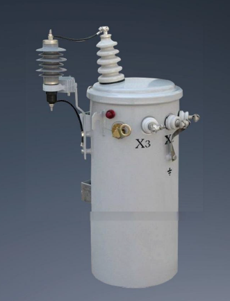
Accurate sizing requires a methodical approach to load evaluation. Follow these steps to translate raw electrical data into a reliable kVA specification.
Aggregate Load Requirements: Start by summing up the power requirements of all connected devices. Check the nameplate on each piece of equipment. If the equipment lists its requirement in amps, simply add the amperage values together. If the equipment lists wattage or kilowatts, you must convert these figures to VA. To convert kW to kVA, divide the kW rating by the power factor of the load. Resistive loads like heaters have a power factor of 1.0. Inductive loads like motors typically have a power factor between 0.8 and 0.9. Dividing by a 0.8 power factor increases the required kVA, reflecting the true current the transformer must supply.
Differentiate Continuous vs. Non-Continuous Loads: Not all electrical loads stress the system equally. You must evaluate the duty cycle of your equipment. The National Electrical Code defines a continuous load as any load operating at maximum current for three hours or more. Lighting systems and HVAC units typically fall into this category. Continuous loads generate sustained heat within the transformer windings. You must apply stricter sizing margins for continuous loads compared to intermittent loads, which allow the unit to cool down between cycles.
Apply the Growth Margin: Never size a transformer to match your load exactly. Operating a unit at 100% capacity continuously causes severe thermal stress. Standard engineering practice requires adding a safety factor to your calculated load. Multiply your total calculated kVA by 1.20 or 1.25. This 20% to 25% margin prevents overheating during minor voltage fluctuations. It also provides built-in capacity for future facility expansion, allowing you to add equipment later without replacing the transformer.
Execute the Real-World Calculation: Let us walk through a practical sizing scenario. Suppose you have a single-phase load that requires 240 Volts. After aggregating your equipment, you determine the maximum current draw is 175 Amps. Multiply Volts by Amps (240 × 175 = 42,000 VA). Divide by 1,000 to find kVA (42,000 / 1,000 = 42 kVA). Your raw load is 42 kVA. If you apply a 20% safety margin, the requirement jumps to 50.4 kVA. Based on standard manufacturing sizes, you would specify a 50 kVA unit if the load is intermittent, or round up to a 75 kVA unit if the load is strictly continuous and expected to grow.
Validate with Digital kVA Calculators: Manual calculations form the foundation of good engineering. Human error can occur during complex load aggregations. Reputable manufacturers provide online digital kVA calculators. Use these tools as a secondary verification step. Input your voltage and amperage data into the calculator to cross-check your manual math. This redundancy ensures you do not order an incorrectly sized unit due to a simple arithmetic mistake.
Medium-voltage distribution networks demand strict adherence to insulation standards. Sizing calculations must align perfectly with primary voltage ratings to ensure safe operation across industrial campuses and utility grids.
Industrial facilities frequently utilize 6kV primary distribution networks. When specifying a 6kV single phase transformer, you must evaluate the Basic Impulse Level (BIL). The BIL dictates the unit's ability to withstand lightning strikes and switching surges. These units require specific tap changer configurations. Off-circuit tap changers allow technicians to adjust the primary voltage ratio by ±5% to compensate for grid voltage drops. You must calculate the kVA accurately to ensure the tap changer functions effectively under full load conditions. If the unit is undersized, adjusting the taps will not fix the resulting secondary voltage sag.
Certain regional grids and specialized industrial environments operate at 6.3kV. Deploying a 6.3kV single phase transformer requires precise primary voltage matching. If you install a standard 6kV unit on a 6.3kV grid, the secondary voltage will run artificially high. This overvoltage condition damages sensitive downstream electronics and shortens the lifespan of lighting ballasts. Conversely, mismatched primary ratings can cause severe secondary voltage drops during peak load times. Your kVA calculation must account for the specific 6.3kV primary input to maintain stable secondary output.
Rural electrification projects and heavy industrial step-down applications often rely on 10kV systems. Sizing a 10kV single phase transformer involves balancing physical footprint against cooling requirements. At 10kV, the dielectric stress on the insulation is significant. You must choose between dry-type and oil-filled cooling methods. Oil-filled units offer superior cooling for higher kVA ratings but require containment basins to prevent environmental contamination. Dry-type units are safer for indoor use but generally have larger physical footprints for the same kVA capacity. Your calculated kVA directly influences which cooling method is viable for your specific installation site.
Field engineers frequently encounter systems suffering from poor sizing decisions. Understanding common pitfalls helps you avoid premature equipment failure and system instability.
Sizing a unit strictly based on running current is a dangerous mistake. Electric motors require a massive surge of power to start turning. This starting kVA (skVA) can be six to ten times higher than the normal running kVA. If your transformer lacks the capacity to handle this sudden demand, the system will experience a severe voltage dip. This voltage drop can cause contactors to chatter, programmable logic controllers (PLCs) to reset, and other motors to stall. You must calculate the maximum skVA of your largest motor and ensure the transformer can supply this surge without dropping the secondary voltage below acceptable limits.
Standard kVA ratings assume specific operating conditions. Manufacturers typically rate units for a maximum ambient temperature of 40°C (104°F) and an altitude below 3,300 feet (1,000 meters). If you install the equipment in extreme environments, you must derate the calculated capacity. High altitudes feature thinner air, which drastically reduces the effectiveness of convective cooling. For every 330 feet above the 3,300-foot threshold, you generally lose 0.3% of the unit's cooling capacity. Failing to apply altitude or temperature derating factors leads to chronic overheating and rapid insulation failure.
Altitude (Feet) | Altitude (Meters) | Derating Multiplier |
|---|---|---|
3,300 | 1,000 | 1.00 (No Derating) |
4,000 | 1,200 | 0.99 |
5,000 | 1,500 | 0.98 |
6,000 | 1,800 | 0.97 |
10,000 | 3,000 | 0.94 |
While undersizing is dangerous, excessive safety margins carry their own penalties. Grossly oversizing a unit leads to significantly higher initial procurement costs. It creates ongoing operational inefficiencies. Transformers experience no-load losses (core losses) simply by being energized, regardless of whether a load is connected. A massive, oversized unit draws more power continuously to magnetize its large core. This lowers the overall system efficiency and increases monthly utility bills. You must strike a balance between adequate safety margins and operational efficiency.
Once you determine your required capacity, you must map that number to commercially available equipment. Custom builds are rarely practical for standard distribution applications due to extended lead times and high engineering costs.
Manufacturers produce equipment in standardized capacity tiers. This standardization streamlines production, reduces lead times, and ensures replacement parts remain accessible. For single-phase applications, the industry universally recognizes specific kVA ratings. Familiarize yourself with these standard sizes to simplify your procurement process.
10 kVA
15 kVA
25 kVA
37.5 kVA
50 kVA
75 kVA
100 kVA
167 kVA
You will rarely calculate a load that perfectly matches a standard rating. The golden rule of transformer sizing is to always round up to the next available standard size. Recall the earlier example where the calculated load was 42 kVA. You cannot order a custom 45 kVA unit without incurring massive engineering fees and extended lead times. Instead, you apply the rounding rule and select the standard 50 kVA unit. This approach guarantees adequate capacity while keeping procurement efficient.
The physical construction of a single phase transformer dictates its thermal limits. The core consists of laminated steel plates, while the coils utilize copper or aluminum winding conductors. The calculated kVA directly influences the size and weight of these internal components. Higher kVA ratings require larger conductors to minimize resistive heating (I²R losses). When you select a standard size, you are choosing a specific core and coil geometry engineered to dissipate heat effectively at that exact capacity. Aluminum windings are lighter and more cost-effective, while copper windings offer a smaller physical footprint and superior fault current withstand capabilities.
Selecting the right kVA is only the first step. You must evaluate the complete nameplate data to ensure system compatibility. Pay close attention to the impedance percentage (%Z). Impedance restricts the flow of short-circuit current. A unit with low impedance allows massive fault currents, requiring heavily upgraded downstream circuit breakers. Verify the temperature rise rating (typically 80°C, 115°C, or 150°C). A lower temperature rise indicates a more robust design with better overload capability. Ensure the unit complies with modern energy efficiency standards to minimize long-term operational losses. If your facility utilizes heavy non-linear loads, you must also check the K-factor rating to ensure the unit can handle the harmonic currents without overheating.
Audit your current electrical load profiles to identify any undocumented equipment additions before specifying a new unit.
Calculate the maximum starting kVA (skVA) for the largest motors in your facility to prevent secondary voltage dips.
Consult with a qualified electrical engineer to verify your duty cycle assessments and environmental derating factors.
Request detailed specification sheets from reputable manufacturers to compare impedance and efficiency ratings prior to procurement.
A: The exact formula is kVA = (V × I) / 1000. You multiply the load voltage (V) by the maximum load current in amperes (I) to get Volt-Amperes. Dividing that total by 1,000 converts the value into kilo-Volt-Amperes, which is the standard rating metric.
A: To convert amps to kVA, you must multiply the total amperage by the specific system voltage. This gives you the total VA. Then, divide that number by 1,000. For example, 100 amps at 240 volts equals 24,000 VA, which converts to 24 kVA.
A: Transformers are rated in kVA because it represents apparent power, which accounts for both real power (kW) and reactive power (kVAR). The transformer's core and coil must physically handle the total current flowing through the system, regardless of the load's power factor.
A: A 20% safety margin prevents the unit from operating at absolute maximum capacity continuously, which causes severe thermal stress. It also accommodates minor voltage fluctuations and provides built-in capacity for future electrical expansion without requiring immediate equipment replacement.
A: An undersized unit will draw more current than its coils can handle. This leads to severe overheating, rapid degradation of the internal insulation, significant secondary voltage drops, and eventual catastrophic failure of the equipment.
A: Motors require a massive surge of power to start, often six to ten times their normal running current. If the transformer is not sized to handle this starting kVA (skVA), the sudden demand will cause severe voltage dips, potentially stalling equipment and resetting control systems.

