


Views: 0 Author: Site Editor Publish Time: 2026-09-03 Origin: Site


Sizing a transformer incorrectly leads to catastrophic overheating, premature failure, or wasted capital on oversized equipment. For facility managers and electrical engineers, calculating the exact kVA (Kilovolt-Amperes) is the foundational step before evaluating procurement options. You cannot afford to guess these parameters. Guessing too low triggers constant breaker trips and fire hazards. Guessing too high locks up valuable project budgets in unused capacity.
You need a reliable, exact mathematical approach. This guide breaks down the standard mathematical formula, real-world safety margins, and commercial selection criteria to help you specify the right industrial transformer. We explore realistic scenarios step-by-step. You will see how ambient conditions affect performance. Ultimately, you will learn how to finalize a specification balancing safety, regulatory compliance, and operational efficiency.
The Baseline Formula: kVA = (Volts × Amps × 1.732) / 1000.
Sizing Reality: Never specify a transformer based on exact peak load; industry standards require a 20% to 25% safety margin.
Commercial Availability: Calculations must be rounded up to the nearest standard manufacturer kVA rating (e.g., 15, 30, 45, 75, 112.5, 150 kVA).
Efficiency Impact: Proper sizing directly influences the operational ROI of an energy saving three phase transformer by optimizing load-to-loss ratios.
Standard single-phase calculations fail in industrial settings. Industrial facilities operate on complex power systems. Three-phase power requires accounting for the square root of 3 (1.732) to accurately measure total power capacity. If you ignore this constant, you calculate the wrong phase relationship. You end up with drastically incorrect sizing data. We rely on a universal industry equation to prevent these foundational errors.
The standard equation is simple but critical. You calculate the required capacity as follows:
kVA = (V × I × √3) / 1000
Let us break down each variable clearly to eliminate confusion:
V (Voltage): This represents the Line-to-Line voltage. Do not use Line-to-Neutral voltage. Using the wrong voltage parameter guarantees a faulty calculation.
I (Amperage): This is the maximum full-load phase current in Amps. It represents the absolute peak power draw your connected equipment requires to operate.
√3 (1.732): The three-phase constant. It mathematically accounts for the three alternating currents operating out of phase.
1000: The standard conversion factor. It translates raw Volt-Amperes (VA) into manageable Kilovolt-Amperes (kVA).
Using this framework guarantees mathematical precision. It creates a solid baseline before you apply any field safety margins. We recommend writing these variables down during every site audit to avoid simple data entry mistakes.
Implementation reality looks different from textbook theory. We must walk through a realistic industrial scenario to transition from theory to practice. Seeing the numbers applied makes the concept instantly clear.
The Scenario: A manufacturing plant is expanding its production line. They need a robust 3 phase transformer to support a new heavy equipment load. The equipment nameplate states it requires 480 Volts and pulls 100 Amps at full capacity.
Here is how we execute the math step-by-step:
Step 1: Multiply the voltage by the amperage. (480V × 100A = 48,000 VA).
Step 2: Multiply that result by the three-phase constant. (48,000 × 1.732 = 83,136 VA).
Step 3: Divide the total by 1000 to convert to kilovolt-amperes. (83,136 / 1000 = 83.14 kVA).
The Result: The raw electrical load requires exactly 83.14 kVA to operate safely. However, this is just the baseline metric. You cannot purchase a unit based solely on this raw number. Doing so invites significant operational risks, as industrial loads rarely remain perfectly stable.
Summary Chart: Calculation Inputs
Parameter | Value | Purpose |
|---|---|---|
Voltage (V) | 480V (Line-to-Line) | Defines the electrical pressure required. |
Amperage (I) | 100A | Defines the volume of electrical current drawn. |
Constant | 1.732 | Adjusts for three overlapping electrical phases. |
Final Output | 83.14 kVA | Represents the absolute minimum capacity needed. |
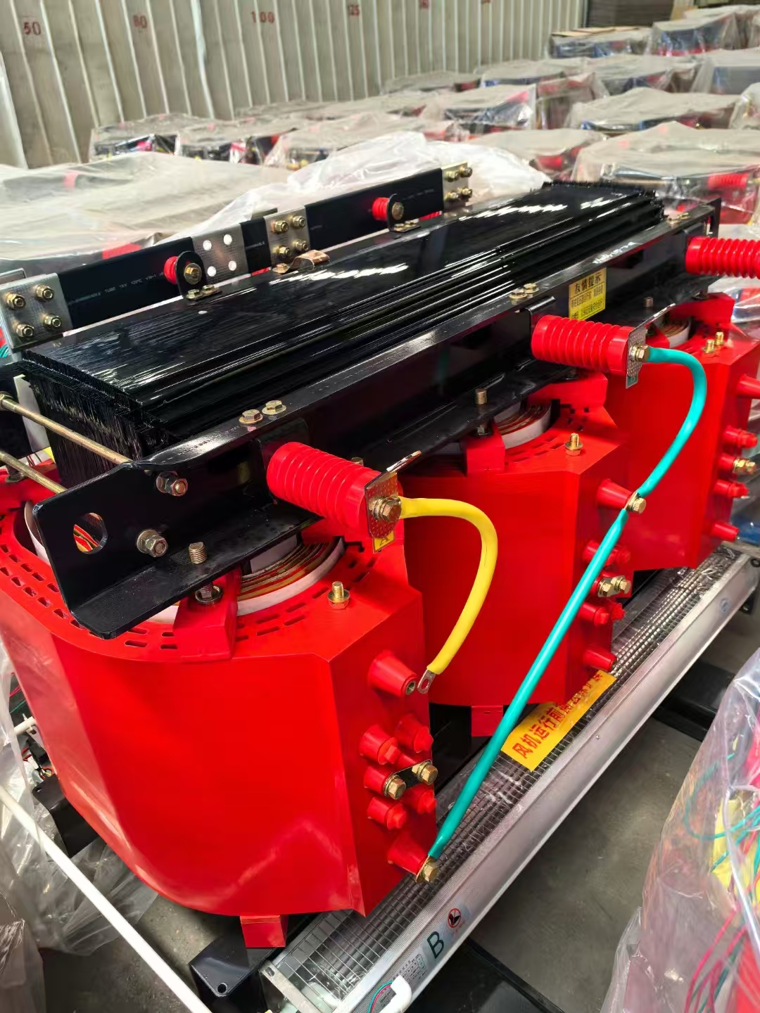
Risk mitigation is crucial in electrical engineering. Specifying an 83.14 kVA unit for an 83.14 kVA load is an engineering flaw. You leave zero room for error. We must apply compliance and safety buffers. Industrial environments fluctuate wildly. Equipment wears down over time. You must anticipate these variables to maintain facility uptime safely.
Industry best practices dictate applying the 20-25% rule. You multiply the raw calculation by 1.20 or 1.25. This safety margin accounts for future facility expansion. It easily handles unexpected transient overloads. It also provides a thermal buffer against internal harmonic heating. Running any electrical equipment at 100% maximum capacity continuously will degrade the insulation rapidly. Heat is the ultimate enemy of electrical longevity.
Let us continue our previous example calculation. We multiply our raw 83.14 kVA by the recommended 1.25 safety factor. The new target capacity becomes 103.92 kVA.
Shortlisting logic dictates your final choice. Manufacturers build these units in standard capacity tiers. You cannot order a custom 103.92 kVA unit without massive unnecessary costs and lead times. A calculated 103.92 kVA load dictates selecting the next standard size up. In this scenario, you specify a 112.5 kVA unit.
Standard Industry 3-Phase kVA Sizes
Calculated Load (kVA) | Safety Target (x1.25) | Recommended Standard Size |
|---|---|---|
22.5 kVA | 28.1 kVA | 30 kVA |
35.2 kVA | 44.0 kVA | 45 kVA |
58.0 kVA | 72.5 kVA | 75 kVA |
83.1 kVA | 103.9 kVA | 112.5 kVA |
115.0 kVA | 143.7 kVA | 150 kVA |
Expertise requires looking beyond pure math. Pure math isn't enough; the specific type of load dictates the final specification. A resistive heating array behaves very differently than a massive conveyor motor. You must categorize your loads correctly to ensure system stability.
Motor loads differ drastically from resistive loads. Resistive loads draw a steady, predictable current. Motor loads behave violently upon start-up. Motor start-ups cause temporary current spikes known as inrush currents. These initial spikes easily exceed nominal kVA calculations. If you size only for the running current, the initial spike will trip your breakers. Severe inrush currents may even damage the internal copper windings over time. You must factor locked-rotor amperage into your calculations for heavy motors.
We must also consider derating for harmonics. Modern plants run high volumes of non-linear loads. Variable Frequency Drives (VFDs) and heavy IT server racks generate significant harmonic distortion. This electrical noise manifests as extreme excess heat inside the core. Highly non-linear environments usually require a K-factor rated unit. A K-factor rating ensures the equipment handles harmonic heat safely. It prevents you from aggressively oversizing the base kVA just to survive temperature spikes.
We must evaluate capacity alongside long-term energy costs. Sizing directly impacts your monthly utility bills. You want to avoid paying for massive unused capacity. Sizing intelligently protects both your equipment and your budget.
These units operate at peak efficiency between 35% and 50% of their rated load. Optimal load capacity keeps core temperatures stable. It maximizes magnetic field efficiency. Oversizing too drastically increases upfront capital. More importantly, it dramatically increases "no-load" core losses. The iron core consumes power constantly, even when your factory machinery sits completely idle.
Once you establish the correct kVA size, focus on technology upgrades. Do not settle for outdated legacy designs. Prioritize a high efficiency three phase transformer to meet stringent DOE and IEC energy regulations. You might also select a low loss three phase transformer featuring an advanced amorphous metal core. These modern materials drastically cut idle power waste. Upgrading to an energy saving three phase transformer ensures maximum operational ROI. It keeps your lifetime operational expenditures as low as mathematically possible while providing clean power.
Troubleshooting builds trust in your facility designs. Address common field errors seen among contractors and engineers. We see the same mistakes repeatedly in industrial deployments. Avoid these specific traps to ensure a flawless installation.
Mistake 1: Confusing Line-to-Line voltage with Line-to-Neutral voltage. This error frequently occurs in 480V/277V systems. If you mistakenly use 277V instead of 480V in your formula, your final result drops drastically. You will order a dangerously undersized unit. Always verify you hold the Line-to-Line metric before doing any math.
Mistake 2: Ignoring site altitude and ambient temperature. Standard manufacturer ratings assume operation below 3,300 feet (1,000 meters). They also assume an ambient environment remaining below 40°C. Operating above 3,300 feet or in extreme heat limits cooling capacity. The thinner air removes heat much slower. You require specific altitude derating calculations to upsize the unit safely under these conditions. Otherwise, the insulation bakes and fails prematurely.
Mistake 3: Failing to verify primary and secondary voltage compatibility. Finding the correct kVA size is only half the battle. The kVA rating remains consistent across the unit. However, the physical connection lugs and internal taps must match your facility's grid precisely. Never finalize a purchase order until you confirm both primary and secondary voltage sides match your exact site layout.
Double-checking these three factors prevents expensive returns and dangerous site failures. Good engineering relies on verifying every assumption.
Calculating 3-phase kVA relies on a straightforward formula: (V × I × 1.732 / 1000). However, finalizing your specification requires deeper engineering awareness. You must factor in a 25% safety margin to protect against thermal degradation. You must account for aggressive inrush currents generated by heavy motors. Finally, you align your mathematical results with standard commercial manufacturing sizes.
Take immediate action on these insights. Finalize your facility load profile sheet today. Itemize every motor and resistive load. Apply your safety multipliers rigorously. Once your documentation is completely verified, consult with a trusted manufacturer. They will review your numbers and help you quote an optimally sized, compliant unit tailored to your exact operational environment.
A: Continuous overloading leads to excessive heat generation inside the core. This heat causes rapid insulation degradation and potential fire hazards. Undersizing also triggers significant voltage drops, which can permanently damage your connected facility machinery and cause frequent breaker trips.
A: You calculate based on the side where the load (amperage) is known. Because the kVA rating is constant across both primary and secondary sides (excluding minor efficiency losses), using either primary V & A or secondary V & A yields the exact same total kVA.
A: A K-factor does not change the base kVA formula. Instead, it indicates the unit's physical ability to withstand extreme heat generated by harmonic currents from non-linear loads. A higher K-factor handles harmonics safely without requiring you to aggressively oversize the base kVA.

