


Views: 0 Author: Site Editor Publish Time: 2026-08-09 Origin: Site


Facility managers and electrical engineers face intense regulatory pressure to eliminate fire hazards and chemical spill risks inside commercial and industrial buildings. Traditional liquid-filled units pose massive containment challenges. You have to build specialized fire vaults, install catch basins, and maintain complex suppression systems. Stepping down high-voltage power safely without these heavy maintenance and containment burdens is the primary operational goal for modern infrastructure. Understanding the exact electromechanical and thermal principles of a dry power transformer is essential. This knowledge lets you evaluate operational limits and match insulation types to specific environmental conditions on site. It also justifies the engineering choices made for the final stage of power voltage reduction before electricity reaches end users. By relying on ambient air and solid dielectrics rather than combustible liquids, these systems offer a fundamentally different, safer approach to facility power distribution.
Operational Mechanism: Dry power transformers utilize electromagnetic induction to step down voltage, relying entirely on ambient air and solid dielectrics for cooling rather than combustible liquids.
Safety and Compliance: The absence of oil inherently makes these units a flame-retardant dry power transformer solution, ideal for indoor installations, hospitals, and commercial high-rises.
Insulation Variability: Selecting between cast resin and vacuum pressure impregnated (VPI) insulation dictates the unit's resilience against moisture, chemical ingress, and mechanical stress.
Configuration Standards: A three-phase dry-type distribution transformer is the industry standard for balancing heavy industrial loads while minimizing footprint and structural reinforcement requirements.
Evaluating efficiency and thermal limits requires a deep understanding of how voltage transforms without a liquid cooling medium. You must identify the core components and their physical interactions to assess system reliability accurately. A dry-type system relies entirely on structural design, precise clearances, and advanced material science to manage electrical stress and heat generation on the facility floor.
The primary and secondary windings act as the conductive coils responsible for receiving high voltage and delivering stepped-down voltage to the facility distribution boards. Manufacturers construct these coils from high-purity copper or aluminum. Copper provides superior electrical conductivity and allows for a smaller physical profile, which helps when electrical room space is tight. Aluminum offers a lighter overall weight and different thermal expansion characteristics, requiring specific lug types and anti-oxidation compounds during termination. The choice between the two directly impacts the unit's final footprint, weight distribution, and termination procedures.
Terminals and bushings serve as the secure connection points interfacing directly with the facility's broader electrical grid. These connection points endure significant mechanical stress during heavy cable installation and daily operation under load. Tap changers are integrated mechanical links that allow for minor voltage adjustments. They compensate for utility grid fluctuations, ensuring stable output to sensitive downstream equipment. Field technicians manually adjust these taps when the transformer is completely de-energized and locked out to fine-tune the delivery voltage before final commissioning.
Voltage reduction relies entirely on the physical interaction between the primary and secondary windings. Alternating current flows into the primary coil from the utility feed. This current generates a rapidly fluctuating magnetic field within the steel core. The secondary coil sits within this exact magnetic field. The fluctuating field induces a voltage in the secondary coil without any physical electrical connection between the two sides. This process operates strictly on the established principles of electromagnetic induction.
Faraday’s Law of Induction governs this voltage reduction for end-user distribution. The ratio of turns in the primary coil to the turns in the secondary coil determines the exact voltage step-down ratio. For low-voltage and medium-voltage applications, maintaining precise turn ratios ensures accurate power delivery to the switchgear. Efficiency metrics depend heavily on minimizing the energy lost as heat during this induction process. Modern core materials minimize hysteresis and eddy current losses, keeping the system efficient and preventing excessive heat buildup in dry environments. When energizing the unit for the first time, the core draws a massive inrush current to establish this magnetic field, requiring engineers to size upstream breakers properly to prevent nuisance tripping.
The magnetic core provides a controlled, low-reluctance path for the magnetic flux generated by the primary winding. Manufacturers construct the core using cold-rolled grain-oriented (CRGO) silicon steel. This specific steel alloy aligns its crystalline structure during manufacturing to offer minimal resistance to magnetic fields. Technicians stack thin laminations of this steel together to form the core structure. They insulate these laminations from one another using a microscopic coating to prevent eddy currents from circulating within the core itself and generating destructive heat.
Core design directly impacts acoustic noise and vibration levels in the electrical room. As the magnetic field fluctuates at 60 Hz, the core laminations physically expand and contract microscopically. This physical movement is called magnetostriction. It produces the characteristic humming sound associated with all transformers. Managing this acoustic noise is a mandatory evaluation criterion for indoor commercial installations like hospitals or office buildings. Engineers utilize precise core clamping techniques, heavy-duty structural bracing, and step-lap joints to reduce vibration and limit noise pollution in occupied spaces. Furthermore, installers must verify the core ground strap is securely attached to the frame to prevent capacitive charge buildup and internal arcing.
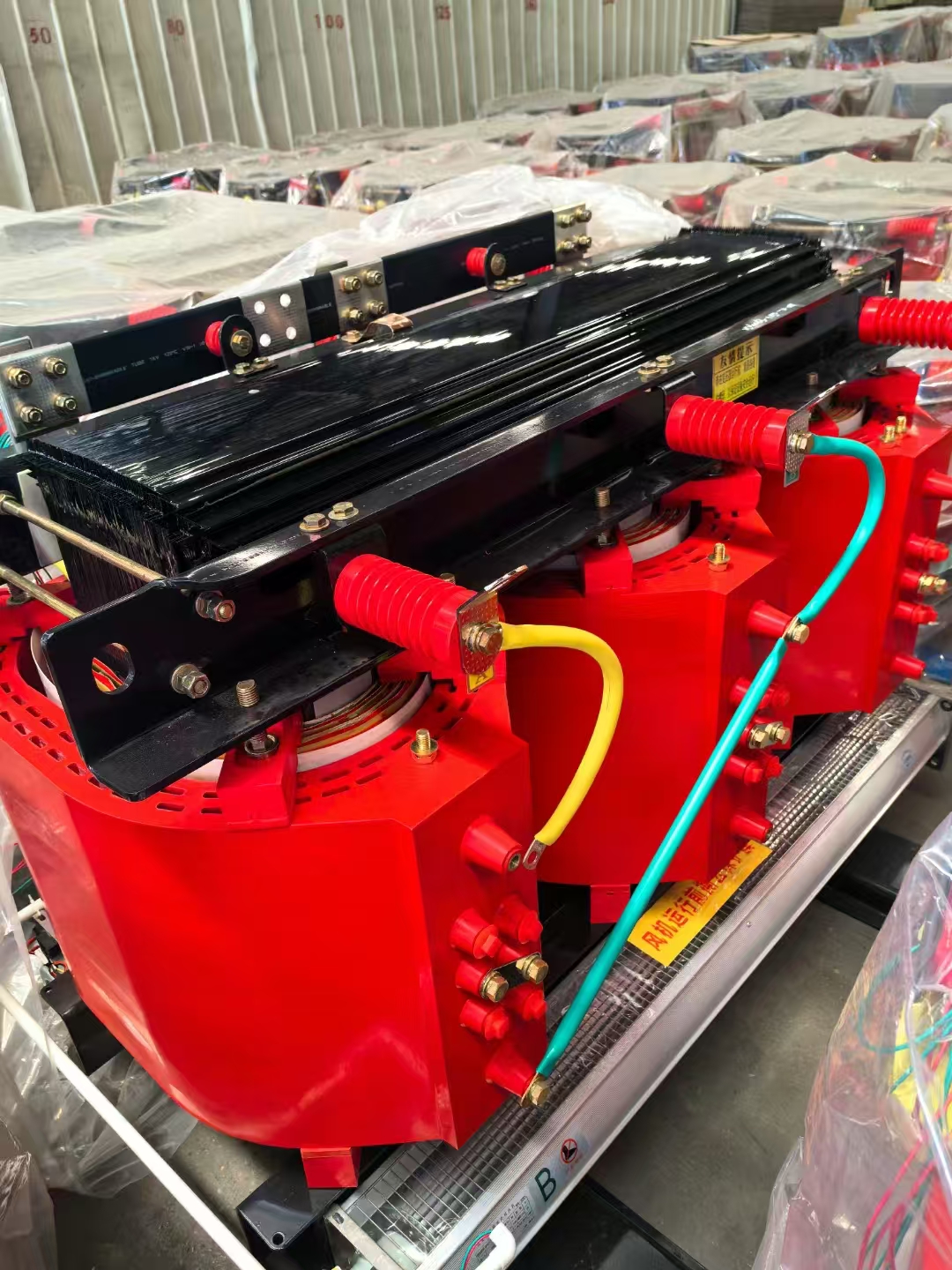
The absence of dielectric fluid shifts the burden of heat dissipation entirely to structural design and ambient airflow. Liquid-filled units use oil to absorb heat and circulate it to external radiators. Dry-type units must rely on the surrounding air to carry heat away from the core and windings. This fundamental difference dictates how you engineer the electrical room ventilation and install the equipment.
Air possesses significantly lower thermal conductivity than mineral oil. Because air cannot transfer heat as efficiently, dry types require larger physical clearances internally. The space between the windings and the core must be wide enough to allow sufficient air circulation. This requirement inherently increases the overall physical dimensions of the unit compared to a liquid-filled counterpart of the exact same capacity.
To prevent short circuits and manage thermal stress, these units rely heavily on high-temperature solid insulation materials. Materials like Nomex paper, fiberglass mesh, and specialized resins wrap the conductive coils. These solid dielectrics maintain their insulating properties even at elevated operating temperatures. Standard temperature rise classifications define the operational limits of these materials above a baseline ambient temperature of 40°C. A lower temperature rise classification indicates a more robust design with greater overload capacity and a longer operational lifespan.
Temperature Rise Class | Maximum Winding Temperature | Hot Spot Allowance | Typical Field Application |
|---|---|---|---|
80°C | 120°C | 30°C | Heavy industrial, high overload requirements, long lifespan priority. |
115°C | 155°C | 30°C | Commercial buildings, balanced cost and overload capacity. |
150°C | 190°C | 30°C | Standard commercial, space-constrained areas, lower initial capital. |
Air Natural (AN) cooling relies entirely on natural convection. As the transformer operates under load, it generates heat. The surrounding air warms up, decreases in density, and rises toward the top of the enclosure. Cooler ambient air is drawn in from the bottom ventilation louvers to replace it. This creates a continuous, passive cooling loop. AN systems are highly reliable because they involve no moving parts and require zero mechanical maintenance.
Air Forced (AF) cooling integrates cooling fans directly into the enclosure base. These fans actively blow ambient air across the core and windings. Implementing AF cooling increases the baseline capacity of the unit significantly. It often yields a 25% to 33% capacity boost over the standard AN rating. Facility managers specify AF systems for peak-load shaving during high-demand periods. The fans activate only when internal thermal sensors detect elevated winding temperatures. Conversely, oversizing an AN unit provides passive reliability without the need to maintain mechanical fans or replace failed fan motors.
Categorizing transformers by their insulation methodology helps engineers match the equipment to specific environmental conditions. Different manufacturing processes yield varying levels of protection against moisture, dust, and mechanical stress. Selecting the correct insulation type ensures long-term reliability and compliance with facility requirements.
The cast resin manufacturing process involves encapsulating the windings entirely in solid epoxy. This process occurs under strict vacuum conditions inside a specialized casting chamber. The vacuum removes all air bubbles and microscopic voids from the resin before it cures. The result is a solid, impenetrable block of insulation surrounding the conductive coils. Specifying a Resin-Insulated Dry Power Transformer provides exceptional durability in demanding environments.
The primary benefits of cast resin technology include near-zero moisture penetration. The solid epoxy prevents humidity from degrading the insulation over time, eliminating the need for space heaters in many applications. Furthermore, the solid casting provides extremely high mechanical strength. It prevents the coils from shifting or deforming under the massive electromagnetic forces generated during a downstream short circuit. These units are highly suitable for polluted, humid, or coastal environments where airborne salt would destroy standard insulation. The trade-offs include a heavier overall weight, a larger physical footprint, and the inability to repair the coils if they fail.
Vacuum Pressure Impregnated (VPI) systems utilize a fundamentally different insulation approach. Manufacturers place the fully assembled coils into a large vacuum chamber. The vacuum removes all moisture and air from the winding layers and insulation paper. Next, the chamber is flooded with a liquid polyester or epoxy varnish. High pressure is then applied to force the varnish deep into the porous insulating materials wrapping the coils. The coils are subsequently baked in an industrial oven to cure the varnish into a solid protective layer.
VPI systems are best suited for clean, dry indoor environments like commercial office buildings or climate-controlled data centers. They offer excellent electrical performance and are generally lighter than cast resin models. Facility managers often prioritize VPI units when budget optimization and repairability are primary concerns. Unlike cast resin coils, which are permanently sealed in epoxy, VPI coils can sometimes be repaired or rewound at a specialized shop if damaged. However, they lack the extreme environmental sealing required for highly corrosive or wet industrial spaces.
Solid insulation materials inherently possess self-extinguishing properties. Unlike mineral oil, which acts as a highly combustible fuel source during a catastrophic failure, solid dielectrics resist ignition. If an internal fault generates an electrical arc, the surrounding materials will not sustain a flame once the arc extinguishes. Utilizing a Flame-Retardant Dry Power Transformer significantly enhances facility safety profiles and simplifies architectural planning.
These units comply with strict international fire codes, including specific IEC and IEEE standards for indoor installations. By utilizing self-extinguishing materials, engineers eliminate the need to construct costly, fire-rated concrete vaults. They also remove the requirement for complex, dedicated fire suppression systems above the transformer installation. This capability drastically reduces overall facility construction complexities and simplifies the integration of heavy power distribution equipment directly into occupied commercial spaces or manufacturing floors.
Translating operational mechanics into practical facility design requires careful load management and spatial planning. Specifying the correct configuration ensures the transformer can handle the electrical demand without overheating. Proper integration also involves selecting the right enclosure to protect the unit while maintaining necessary airflow.
Industrial and commercial facilities almost exclusively utilize three-phase power for heavy equipment and general distribution. A Three-Phase Dry-Type Distribution Transformer handles these heavy loads efficiently. Three-phase systems transmit power using three alternating currents that are offset in time by 120 degrees. This provides a continuous, smooth power delivery to large motors and switchgear. Engineers configure the primary and secondary windings in either Delta or Wye connections. Delta configurations are common for primary high-voltage connections. Wye configurations on the secondary side provide a neutral point, allowing for both three-phase and single-phase load distribution across the facility.
Load profiling is a mandatory step in the sizing process. Engineers must match the transformer's kVA rating to the facility's continuous and non-linear loads. Non-linear loads include modern electronic equipment, LED lighting drivers, data center servers, and variable frequency drives (VFDs). These devices draw current in abrupt pulses rather than smooth sine waves. This creates harmonic distortion within the electrical system. Harmonic distortion generates excess heat within the transformer core and windings. Engineers address this by specifying K-factor ratings. A K-rated transformer features specialized winding designs, heavier conductors, and modified transposition techniques specifically engineered to handle the thermal stress of harmonic loads without degrading.
The enclosure protects the internal components from environmental hazards and prevents accidental personnel contact with live electrical busbars. The National Electrical Manufacturers Association (NEMA) defines enclosure standards. Selecting the correct enclosure dictates how well the unit breathes and survives in its installed environment.
Ventilation requirements dictate the physical placement of the unit within the electrical room. Because dry types rely on ambient air for cooling, calculating clearance requirements is mandatory. Engineers must ensure adequate spacing from walls, ceilings, and other equipment. Blocking the ventilation louvers disrupts the convective cooling loops. Insufficient airflow causes the internal temperatures to spike, leading to premature insulation failure. Proper facility design incorporates dedicated ventilation pathways, exhaust fans, and intake louvers to supply cool air and exhaust the massive amount of heated air generated by the transformer under full load.
NEMA Enclosure Type | Installation Environment | Protection Level Provided | Cooling Impact |
|---|---|---|---|
NEMA 1 | Clean Indoor | Protects against falling dirt and accidental personnel contact. | Maximum airflow through large ventilation louvers. |
NEMA 2 | Indoor with Drip Risk | Adds drip shields to protect against light splashing or condensation. | Slightly restricted top airflow due to drip shields. |
NEMA 3R | Outdoor | Protects against rain, sleet, and snow damage. | Requires specialized louvers that restrict airflow, often requiring derating. |
NEMA 4/4X | Harsh Outdoor / Washdown | Watertight and dust-tight. 4X adds corrosion resistance. | Totally enclosed non-ventilated (TENV). Relies entirely on surface cooling. |
Addressing the realistic vulnerabilities of dry-type systems ensures long-term operational stability. While these units eliminate the hazards of liquid dielectrics, they introduce different maintenance requirements. Facility teams must plan for these specific environmental and operational factors to maximize equipment lifespan.
Dry units generally require a larger physical footprint than liquid-filled units of the exact same kVA rating. The need for wider internal air channels dictates this larger size. Facility designers must allocate sufficient floor space in electrical rooms to accommodate the equipment and its required ventilation clearances. You cannot push these units flush against a wall. However, this larger footprint is often offset by the elimination of fluid containment basins and fire-rated separation walls. The overall spatial requirement for the electrical room can sometimes decrease when you remove the ancillary safety infrastructure required for liquid units from the architectural plans.
Dry-type systems require a strict, predictable maintenance schedule to survive their intended 20 to 30-year lifespan. Facility teams must conduct periodic thermal imaging inspections while the unit is under normal load. Infrared cameras detect hot spots on terminal connections or winding surfaces, indicating loose hardware or degraded insulation. Technicians must perform regular torque checks on all electrical connections during scheduled shutdowns. Thermal cycling causes metal components to expand and contract, which loosens bolts over time and increases contact resistance.
The most critical maintenance task is vacuuming dust and debris from the cooling channels. Accumulated dust acts as a thermal insulator. It traps heat against the windings and restricts natural airflow. Technicians must execute the following maintenance sequence annually:
De-energize the transformer and apply proper lockout/tagout (LOTO) procedures.
Remove the enclosure panels to access the core and coil assembly.
Use dry compressed air (under 25 psi) to blow loose dust out of the winding ducts.
Use industrial vacuums with non-metallic attachments to remove all debris from the enclosure base.
Inspect the solid insulation for any signs of cracking, tracking, or discoloration.
Verify the torque on all primary and secondary busbar connections using a calibrated torque wrench.
Reinstall all panels and verify the area is clear before re-energizing.
Non-resin units exhibit susceptibility to specific environmental hazards. Heavy dust accumulation, chemical vapors, and high moisture levels can degrade VPI insulation over time. Airborne contaminants can settle on the windings and create tracking paths for electrical currents, potentially leading to a catastrophic short circuit.
Mitigation strategies begin with proper enclosure selection. If the environment contains heavy particulates, engineers may specify a totally enclosed non-ventilated (TENV) design, though this severely limits the kVA capacity. To combat moisture, facility teams install space heaters inside the enclosure. These heaters activate automatically when the transformer is de-energized. They maintain the internal temperature slightly above the ambient dew point, preventing condensation from forming on the cold windings. Utilizing advanced filtration on the facility's main HVAC intake vents also reduces the volume of particulates reaching the electrical room.
A dry power transformer is the definitive choice for indoor, commercial, and environmentally sensitive applications. The inherent fire safety and the elimination of liquid containment protocols streamline facility design and reduce ongoing compliance burdens. By understanding the core electromechanical principles, engineers can accurately match insulation technologies to specific environmental demands.
Choose VPI systems for clean, climate-controlled environments to optimize project budgets. Specify cast resin insulation for harsh, humid, or high-vibration industrial settings where maximum durability is required. Proper load profiling and enclosure selection guarantee the system operates within its thermal limits.
Conduct a comprehensive facility load analysis to determine the exact continuous and non-linear power requirements.
Calculate the required CFM for electrical room ventilation to handle the anticipated heat rejection.
Specify the necessary NEMA enclosure ratings based on the specific indoor or outdoor installation environment.
Establish a strict annual maintenance schedule focused on thermal imaging and cleaning internal cooling channels.
A: A standard unit typically operates reliably for 20 to 30 years. This lifespan is entirely contingent on operating within the specified temperature limits and maintaining clean internal cooling channels. Excessive heat from overloading or blocked airflow accelerates insulation degradation and shortens the equipment's usable life.
A: Yes, you can install them outdoors. While primarily designed for indoor use, outdoor installation requires a proper NEMA 3R or NEMA 4 enclosure to protect against precipitation. Engineers strongly recommend utilizing cast-resin insulation for outdoor units to prevent moisture ingress during periods of high humidity.
A: They lack the sound-dampening properties of mineral oil. In liquid units, the heavy oil absorbs core vibration and magnetostriction noise. In dry units, these vibrations travel easily through the ambient air and transfer directly to the metal enclosure, resulting in a more noticeable humming sound in the electrical room.
A: The difference lies in the insulation manufacturing process. VPI involves dipping the coils in varnish under vacuum and pressure, making it suitable for clean indoor spaces. Cast resin involves encapsulating the coils completely in solid epoxy, providing superior protection against harsh chemicals, moisture, and extreme mechanical stress.
A: Yes. While considered low maintenance because they lack fluid, they require strict annual inspections. Technicians must de-energize the unit to vacuum dust accumulation from the cooling channels, verify connection tightness with a torque wrench, and inspect the solid insulation for signs of thermal degradation.
A: It handles harmonic loads through specific K-factor ratings. Non-linear loads create harmonic distortion that generates excess heat. K-rated units utilize specialized core designs, heavier winding conductors, and modified transposition techniques to mitigate this overheating and maintain stable power delivery under distorted load conditions.
A: The primary components include the magnetic steel core, the primary and secondary conductive windings, the solid dielectric insulation materials, the protective metal enclosure, the terminal connection points, and the tap changers used for minor voltage regulation during commissioning.

