


Views: 0 Author: Site Editor Publish Time: 2026-08-18 Origin: Site


Facility uptime, infrastructure safety, and long-term operational costs tie directly to primary power distribution equipment specifications. Selecting the wrong transformer type for a specific environment leads to severe consequences. You might face fire code violations, excessive maintenance overhead, or premature equipment failure. In worst-case scenarios, incorrect selection causes catastrophic environmental hazards. Electrical engineers and facility managers must evaluate their options carefully.
This guide provides a strict technical and financial comparison between dry and liquid-filled units. We evaluate them on thermal performance, voltage limitations, lifecycle costs, compliance requirements, and application suitability. We examine the specific engineering trade-offs required for different installation environments. This comprehensive analysis helps drive an evidence-based procurement decision. You will learn how to match transformer technology to your exact load profile and safety mandates.
Application Dominance: Dry power transformers are the definitive standard for indoor, commercial, medium-to-low voltage, and high-density environments due to the elimination of fire vaults and spill containment requirements.
Performance Scaling & Voltage Limits: Oil-filled transformers maintain a distinct advantage in raw cooling efficiency, temporary overload capacity, acoustic dampening, and high-voltage capacity, making them optimal for large-scale outdoor utility deployments.
Lifecycle Economics: While oil-filled units often have a lower initial unit cost, dry types frequently deliver lower lifecycle costs in commercial settings by eliminating fluid maintenance, spill prevention equipment, and complex installation infrastructure.
Efficiency Advancements: Specifying modern cast resin models (such as the SCB13 or SCB14) significantly narrows the historical energy efficiency gap between dry and liquid-filled technologies.
Transformer selection requires a rigorous evaluation of your facility requirements. You cannot rely on generic assumptions. Every installation presents unique electrical, physical, and regulatory challenges. Establishing clear success criteria prevents costly design revisions later. Engineers must look at the entire power distribution network before specifying the transformer type.
You must define specific operational parameters before evaluating transformer types. These parameters dictate the necessary dielectric and thermal properties. Consider the following baseline criteria when planning your electrical infrastructure:
Define the facility load profile. Calculate peak demand expectations accurately. Account for harmonic distortion levels generated by non-linear loads like variable frequency drives and LED lighting networks.
Determine the required voltage class. Differentiate between medium or low voltage distribution and high-voltage transmission needs.
Assess the installation environment thoroughly. Decide between indoor or outdoor placement. Note ambient temperature extremes, site altitude, and available ventilation capacity.
Identify strict regulatory compliance requirements. Review local fire safety codes. Check environmental protection mandates regarding fluid containment.
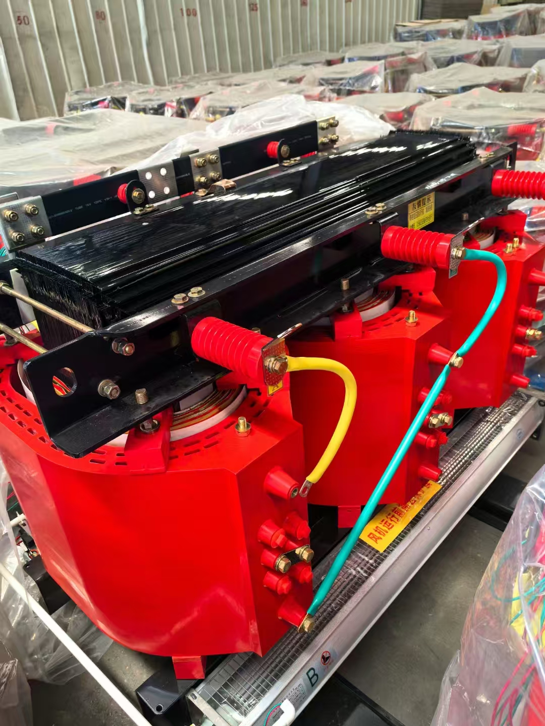
A dry power transformer operates without liquid cooling mediums. It utilizes natural air convection or forced air cooling. The system relies entirely on solid insulation. Manufacturers typically use cast resin or Vacuum Pressure Impregnated (VPI) techniques. The core and coils sit within ventilated or sealed enclosures. They do not use liquid dielectrics. The cast resin process encapsulates the high-voltage windings in a solid epoxy block under vacuum, eliminating air voids and providing immense mechanical strength.
This design offers distinct environmental and safety advantages. It is inherently non-flammable. The materials remain environmentally inert. The unit poses zero risk of fluid leakage. This makes it optimized for medium and low voltage applications. Engineers typically specify them for systems up to 35kV. They excel in commercial buildings, hospitals, and underground transit systems where fire safety is the primary concern.
Oil-filled transformers utilize a fundamentally different cooling mechanism. They submerge the magnetic core and copper coils in dielectric fluid. This fluid is usually highly refined mineral oil or synthetic ester. The components sit within a hermetically sealed steel tank. The liquid provides exceptional dielectric strength. It also enables rapid, highly efficient heat dissipation through convection currents that move hot oil to external cooling radiators.
This liquid-cooled approach provides superior thermal capacity. It allows for a much more compact core-to-coil ratio. The fluid handles immense electrical stress effectively. This allows manufacturers to build massive kVA ratings. These units handle extreme high-voltage applications easily, often scaling up to 765kV. They dominate the utility grid and heavy industrial sectors where physical space and fire codes are less restrictive.
Comparing these technologies requires looking past basic specifications. You must translate physical features into operational outcomes. Thermal dynamics, acoustics, and physical footprint dictate installation feasibility. A unit that looks perfect on a spec sheet might fail completely once installed in a confined electrical room.
Heat transfer dynamics differ vastly between liquid cooling and air convection. Liquid transfers heat much faster than air. Oil circulates through the transformer tank via natural or forced convection. It pulls heat away from the coils rapidly and transfers it to the external tank walls or radiator fins. Air cooling relies on ambient airflow across exposed coil surfaces. This process is inherently slower and less efficient, requiring larger cooling ducts between the windings.
Thermal mass plays a critical role in handling load spikes. Oil-filled units contain a large liquid volume. This fluid acts as a massive thermal buffer. It absorbs temporary heat spikes efficiently. The liquid dissipates thermal overloads better than solid insulation. This makes liquid units highly resilient during temporary peak demands, such as starting large industrial motors.
Ambient temperature heavily impacts dry type performance. High ambient heat reduces the cooling efficiency of natural air convection. Engineers must often derate dry units in hot environments. Forced-air fan systems become necessary for peak load management. These cooling fans increase the effective kVA rating temporarily, often by up to 33%. However, they introduce moving parts and additional maintenance points to the system.
Transformer noise originates from the magnetic core. Alternating current causes the core laminations to expand and contract. This phenomenon is called magnetostriction. It generates a continuous low-frequency hum, typically at twice the line frequency. The cooling medium heavily influences how this sound travels from the core to the surrounding environment.
Liquid dielectrics act as natural acoustic dampeners. The heavy oil surrounds the vibrating core completely. It suppresses core and coil vibration effectively. The sealed steel tank provides another layer of sound insulation. Therefore, oil-filled units are inherently quieter than their dry counterparts. They transmit far less structural vibration into the concrete pad.
Dry units lack this liquid dampening layer. The sound waves travel directly through the air. Acoustic mitigation strategies become necessary for commercial building installations. Engineers must specify vibration isolation pads under the unit. Strategic room placement is critical to avoid resonant frequencies. In sensitive environments like hospitals or recording studios, sound-attenuating enclosures may be required to meet acoustic standards.
Physical dimensions often dictate transformer selection in existing facilities. You must evaluate both the base unit size and the total installation footprint. Retrofitting older buildings often forces engineers to choose equipment based entirely on what fits through the loading dock doors.
Dry types are physically larger and heavier per kVA. Air possesses a lower dielectric strength than oil. Therefore, dry units require larger air clearances between internal components to prevent arcing. The solid insulation also adds significant bulk. This increases the overall base dimensions and weight of the equipment, requiring heavier floor loading capacities in multi-story buildings.
However, oil-filled units ultimately require more total real estate. The base unit might be smaller, but the installation requirements are massive. Safety regulations mandate extensive external infrastructure. You must build containment dikes to catch potential fluid spills. Blast walls are often required between adjacent units. Fire clearances demand significant empty space around the transformer. This makes liquid units difficult to place in tight urban environments.
Evaluation Metric | Dry Type Transformer | Oil-Filled Transformer |
|---|---|---|
Cooling Medium | Air (Natural or Forced) | Mineral Oil or Synthetic Fluid |
Overload Capacity | Moderate (Requires Fans for Peak) | High (Excellent Thermal Mass) |
Acoustic Profile | Louder (Requires Dampening Pads) | Quieter (Oil Absorbs Sound Waves) |
Base Unit Size | Larger per kVA (Wider Clearances) | More Compact per kVA |
Total Footprint | Minimal (No Vaults Needed) | Extensive (Dikes, Fire Walls Required) |
Dielectric Strength | Lower (Relies on Air/Resin) | Higher (Liquid Insulation) |
Safety regulations drive many procurement decisions. Fire codes and environmental protection laws dictate where certain equipment can operate. Ignoring these compliance factors leads to severe legal and financial penalties. Facility managers must prioritize life safety and environmental stewardship when selecting high-voltage equipment.
Standard transformer oils pose a significant fire risk. Mineral oil has a specific flashpoint, typically around 145°C. If internal faults generate enough heat, the oil can ignite. This creates an intense, difficult-to-extinguish chemical fire. Conversely, cast resin materials possess self-extinguishing properties. They do not support combustion. They will not propagate a fire if an electrical fault occurs, making them inherently safer for occupied structures.
The National Electrical Code (NEC) strictly regulates indoor transformer installations. Installing an oil-filled unit indoors triggers massive compliance costs. The code requires a dedicated 3-hour fire-rated vault. You must construct thick concrete walls and specialized fire doors. You also need heavy-duty ventilation systems and liquid containment sills. Dry units bypass these costly architectural requirements entirely, allowing for installation on open factory floors or standard electrical rooms.
Environmental protection agencies monitor dielectric fluids closely. The EPA enforces strict regulations regarding oil leaks. Facilities must maintain active Spill Prevention, Control, and Countermeasure (SPCC) plans if they store large volumes of oil. A ruptured tank can cause severe soil contamination. It threatens local groundwater supplies immediately. Remediation efforts cost hundreds of thousands of dollars and cause massive public relations damage.
Ecologically sensitive zones mandate dry technology. You must use dry units in marine environments. They are required near water treatment facilities. They are standard in protected wildlife areas. The absence of liquid eliminates the spill risk entirely. This provides immense peace of mind for facility operators managing sites near rivers, lakes, or coastal regions.
End-of-life disposal processes also differ significantly. Degraded transformer oil requires hazardous material handling. You must hire specialized chemical disposal contractors. The tank requires extensive decontamination before scrapping. Scrapping cast resin and VPI dry types is much simpler. The copper or aluminum coils are easily separated and recycled. The solid resin poses no chemical hazard during disposal, reducing decommissioning liabilities.
Energy efficiency standards have evolved rapidly. Older dry units suffered from higher core losses than liquid units. Modern materials and manufacturing techniques have closed this gap. Understanding these efficiency tiers is crucial for long-term operational savings. Selecting the right tier depends entirely on your facility's continuous load profile.
Epoxy resin casting revolutionized dry transformer reliability. Manufacturers cast the high-voltage coils in a vacuum chamber. This process eliminates microscopic air voids within the insulation. The solid epoxy protects the copper coils from moisture ingress. It blocks corrosive dust and chemical vapors effectively, allowing these units to operate in harsh industrial environments that would have previously required sealed oil units.
This rigid casting provides immense mechanical strength. It prevents coil movement during severe short-circuit events. The solid block also improves thermal conductivity. It transfers heat from the internal conductors to the surface efficiently. This allows for higher kVA ratings in smaller physical enclosures, pushing the boundaries of what air-cooled technology can achieve.
Engineers specify different efficiency tiers based on load profiles. Continuous high loads justify premium efficiency models. Intermittent loads might only require standard baseline units. You must match the core technology to your actual operational demands.
The SCB11 Dry Power Transformer represents the baseline standard. It is designed for general industrial and commercial use. It offers highly reliable performance and robust construction. However, it features standard loss profiles. It utilizes traditional silicon steel cores. It is highly effective for facilities with lower continuous demand or standby applications where no-load losses are less critical.
The SCB13 Dry Power Transformer represents a significant step up in performance. It features highly optimized magnetic core materials. The winding designs are refined to reduce electrical resistance. This results in significantly reduced no-load core losses. It improves overall energy efficiency substantially. It is ideal for modern commercial buildings seeking green energy certifications and lower monthly utility bills.
The SCB14 Dry Power Transformer sits at the premium efficiency tier. It utilizes advanced, high-grade silicon steel. Some models incorporate amorphous metal cores with random atomic structures that drastically reduce hysteresis losses. These materials deliver the absolute lowest energy losses available. It provides the best financial return for continuous, high-load applications like data centers and continuous manufacturing plants.
Transformer Model | Core Material Technology | Efficiency Profile | Best Application Scenario |
|---|---|---|---|
SCB11 Series | Standard Silicon Steel | Baseline Efficiency | Standby power, intermittent industrial loads |
SCB13 Series | Optimized Silicon Steel | High Efficiency | Commercial buildings, hospitals, schools |
SCB14 Series | Advanced/Amorphous Metal | Premium Efficiency | Data centers, continuous manufacturing |
Financial evaluation requires looking beyond the purchase order. You must calculate the total financial impact over the equipment's lifespan. Initial capital expenditure rarely tells the whole story. Long-term operating expenses dictate the true cost of the asset. Facility managers must bridge the gap between construction budgets and maintenance budgets.
Dry types generally carry a higher base manufacturing cost. The cast resin process is complex and material-intensive. Equivalent oil-filled units are often cheaper to manufacture due to simpler core-and-coil assemblies dropped into steel tanks. If you only compare the unit price, oil appears more economical. However, installation offsets change the financial equation drastically.
Eliminating architectural requirements lowers the actual installed cost. Dry units do not require fireproof concrete vaults. You do not need to excavate catch basins or pour extensive containment dikes. Specialized fluid routing and fire suppression equipment are unnecessary. When you factor in construction labor, concrete, and specialized fire doors, dry units are often cheaper to install indoors.
Routine maintenance impacts operating budgets heavily. Oil-filled units demand labor-intensive upkeep. You must perform annual oil sampling. Technicians must conduct Dissolved Gas Analysis (DGA) to check for internal faults. The fluid requires periodic filtration and dehydration to maintain dielectric strength. You must inspect tank seals, radiators, and pressure relief valves for leaks constantly.
Dry types require minimal maintenance. They need an annual visual inspection. Technicians should vacuum accumulated dust from the cooling channels. You must check the torque on electrical connections. There are no fluids to test, filter, or replace. This reduces annual maintenance budgets significantly and frees up facility personnel for other critical tasks.
Lifespan expectations vary based on maintenance rigor. Oil-filled units can operate for 30 or more years. However, this requires strict, expensive fluid maintenance. Dry types offer a highly reliable 20-to-25-year lifespan. They achieve this with virtually zero maintenance overhead. Upgrading to an SCB14 model reduces energy losses, generating monthly utility savings that compound over two decades.
No technology is immune to failure. Both transformer types face specific environmental vulnerabilities. Identifying these risks early allows you to implement effective mitigation strategies. Proactive engineering prevents catastrophic downtime and extends the operational life of your distribution equipment.
Dry units rely on clean air for cooling and insulation. Dust accumulation poses a severe risk. Heavy dust blocks the air cooling pathways between coils. This causes localized overheating and accelerates insulation degradation. High humidity presents another major threat. Moisture can combine with dust to create conductive tracks on the resin surface. This leads to tracking and eventual dielectric breakdown.
You must specify the correct NEMA or IP enclosure rating. Standard ventilated enclosures work for clean indoor environments. Harsh industrial settings require totally enclosed, non-ventilated designs. Ensure the electrical room has adequate HVAC ventilation and filtration. Enforce strict, routine cleaning schedules. Technicians must remove dust using dry compressed air and industrial vacuums during scheduled facility shutdowns.
Liquid dielectrics degrade over time under thermal and electrical stress. Sludge formation is a primary risk. Oxidation causes the oil to break down and form solid sludge. This sludge coats the internal coils and blocks cooling channels, trapping heat against the paper insulation. Moisture ingress also reduces the dielectric strength of the oil drastically. These factors lead to internal arcing and catastrophic tank rupture.
Implement strict, condition-based monitoring programs to mitigate this. Do not rely on run-to-failure strategies. Schedule regular DGA testing to detect trace gases like hydrogen and ethylene. These gases indicate specific types of internal faults before they cause a failure. Utilize proactive oil reclamation services. Filter the oil to remove moisture and particulate matter before sludge forms.
Take the following actions to finalize your procurement strategy:
Conduct a comprehensive site audit to map exact physical space, floor loading limits, and ventilation constraints.
Calculate total lifecycle expenditures, factoring in 20 years of maintenance, energy losses, and initial construction offsets.
Consult with a licensed electrical engineer to specify the exact kVA rating and primary/secondary voltages needed.
Evaluate your load profile to determine if an SCB13 or SCB14 efficiency tier offers the best long-term financial return.
Review local fire codes and environmental regulations to confirm compliance requirements for your specific installation zone.
A: Historically, oil-filled units held the efficiency advantage due to superior core-to-coil ratios and liquid cooling. Modern premium cast resin models utilize advanced amorphous metal cores. These modern dry units achieve efficiency levels that rival or exceed standard liquid-filled units, especially in medium-voltage applications.
A: Dry types are typically limited to medium and low voltage applications, generally maxing out around 35kV to 46kV. The air clearance required for higher voltages makes them physically impractical. Oil-filled units handle extreme high-voltage transmission, easily scaling up to 765kV for massive utility grid deployments.
A: Yes, you can install them outdoors, but they require specialized weather-resistant enclosures. You must specify high NEMA or IP ratings (like NEMA 3R or NEMA 4) to protect the solid insulation from rain, snow, and wind-blown debris. Standard ventilated indoor models will fail quickly if exposed to outdoor elements.
A: A well-maintained liquid-filled transformer can operate for 30 to 40 years, provided you perform rigorous fluid filtration and testing. Dry types generally offer a reliable 20 to 25-year lifespan. While the dry type lifespan is slightly shorter, it requires virtually zero maintenance overhead to reach that operational milestone.
A: The heavy dielectric liquid inside an oil-filled unit acts as a natural acoustic dampener. It surrounds the magnetic core and absorbs the low-frequency vibrations caused by magnetostriction. Dry types lack this liquid barrier, allowing sound waves to travel directly through the air, requiring external acoustic mitigation.
A: These designations represent ascending energy efficiency tiers. The SCB11 is the baseline model with standard silicon steel cores. The SCB13 features optimized winding and core designs for lower no-load losses. The SCB14 is the premium tier, utilizing advanced magnetic materials to deliver the absolute lowest energy losses for continuous high loads.
A: Maintenance is minimal but critical. You must perform an annual visual inspection of the cast resin for cracks or tracking. Technicians must vacuum dust and debris from the cooling channels to prevent overheating. Finally, you should verify the torque on all electrical connections and ensure cooling fans operate correctly.

