


Views: 0 Author: Site Editor Publish Time: 2026-08-22 Origin: Site


Industrial power distribution in remote or localized applications demands precise voltage regulation. Three-phase infrastructure often proves unavailable or economically unviable in these isolated areas, forcing engineers to rely on dedicated single-phase networks. Procuring an under-specced or inefficient unit leads to accelerated thermal degradation. You face unacceptable no-load losses and severe operational downtime that halts production lines. Selecting the optimal equipment requires a rigorous evaluation of core design architectures. You must analyze winding materials, thermal management capabilities, and strict vetting protocols. We will break down how to specify, evaluate, and procure the exact hardware for your site requirements. You will learn actionable strategies for load profiling, environmental casing selection, and condition monitoring. Proper specification ensures reliable power delivery under harsh industrial conditions, keeping your facility running without unexpected thermal failures or voltage drops.
Efficiency Dictates TCO: Lifecycle operational costs heavily outweigh initial capital expenditure; prioritizing low no-load (iron) losses is critical for long-term ROI.
Core Architecture Matters: Advanced wound core designs, such as the D11-M(R) transformer, offer significant reductions in magnetic reluctance and excitation current compared to traditional stacked cores.
Vendor Accountability & Verification: A reliable single phase transformer manufacturer must provide transparent Factory Acceptance Testing (FAT) data, and procurement teams must employ structured information search methodologies to verify digital datasheets and certifications.
Risk Mitigation: Successful implementation relies on accurate kVA sizing, appropriate environmental casing (e.g., NEMA/IP ratings), proactive thermal management strategies, and smart condition monitoring.
Accurate load profiling prevents premature equipment failure. Engineers must calculate both continuous load and peak demand. Continuous load represents the steady-state power draw over a 24-hour cycle. Peak demand accounts for motor starting currents and intermittent heavy machinery usage. You must apply a diversity factor to avoid massive over-sizing. Over-sizing directly exacerbates no-load losses. The core remains energized continuously, consuming power even when downstream equipment sits idle.
Follow this structured approach for capacity sizing:
Audit all connected devices to determine total running wattage.
Identify the largest motor load to calculate the maximum inrush current.
Apply a diversity factor based on the realistic simultaneous operation of your equipment.
Add a 20% safety margin for future capacity expansion.
Do not exceed this margin without a concrete expansion timeline. Non-linear industrial loads introduce harmonic distortion. Variable Frequency Drives (VFDs) and heavy rectifiers generate significant harmonics. These harmonics increase skin effect losses in the windings. Specify a K-factor rating if your facility operates extensive non-linear equipment. A K-rated single phase transformer features upgraded winding conductors and enhanced core cooling to handle harmonic heating.
Many industrial sectors operate where three-phase power remains unviable. Railway signaling systems rely heavily on single-phase networks spanning hundreds of miles. Remote mining operations often tap into single-phase overhead lines for localized extraction equipment. Isolated oil and gas pumping stations utilize single-phase units to power telemetry and valve actuators. Each application demands unique voltage specifications.
Dual-voltage capabilities provide operational flexibility. A unit might step down 14.4 kV to either 240V or 120V depending on the tap configuration. Specialized step-down ratios support legacy machinery. Evaluate your exact secondary voltage requirements before finalizing the specification. Mismatched secondary voltages require additional step-down equipment, increasing system complexity and energy losses.
Physical footprint limitations dictate the mounting configuration. Pole-mounted units save ground space but face strict weight limits. Pad-mounted configurations accommodate higher kVA ratings but require secure concrete foundations. Assess the deployment site for environmental stressors. Corrosive atmospheres in chemical plants demand stainless steel enclosures. Extreme ambient temperatures require specialized insulation fluids or high-temperature solid insulation.
Seismic zones mandate reinforced mounting brackets and flexible bushing connections. High-altitude deployments require derating. Air density drops above 1,000 meters, reducing cooling efficiency and dielectric strength. Standard IEC guidelines recommend derating the kVA capacity by 1% for every 100 meters above the 1,000-meter threshold.
Enclosure Rating | Primary Protection | Typical Industrial Application |
|---|---|---|
NEMA 3R | Rain, sleet, and snow. | Standard outdoor substations and pole mounts. |
NEMA 4 | Hosedown and splashing water. | Wash-down areas in food processing or mining. |
NEMA 4X | Corrosion resistance and hosedown. | Chemical plants, coastal facilities, and wastewater. |
NEMA 12 | Dust, falling dirt, and dripping non-corrosive liquids. | Indoor manufacturing floors and assembly lines. |
Core architecture fundamentally determines electrical efficiency. Traditional stacked cores utilize flat steel laminations cut into rectangular shapes. Workers interleave these laminations to form the magnetic circuit. This construction method inherently creates microscopic air gaps at the joints. Air gaps increase magnetic reluctance. Higher reluctance demands more excitation current, driving up no-load losses.
Wound core designs eliminate these joints. Manufacturers wind a continuous strip of electrical steel around a mandrel. This creates an uninterrupted magnetic flux path. Hysteresis and eddy current losses drop significantly. The continuous grain orientation of the steel aligns perfectly with the magnetic field. Wound cores operate cooler and quieter than their stacked counterparts.
The D11-M(R) transformer represents a major leap in wound core technology. It utilizes a three-dimensional rolled core design. The cross-section of the core legs forms a near-perfect circle. This geometry optimizes the winding process. Circular windings distribute mechanical stress evenly during short-circuit events.
The continuous magnetic circuit eliminates air gaps entirely. Excitation current drops by up to 70% compared to legacy D9 or D10 series models. No-load losses decrease by approximately 30%. The seamless flux path also mitigates magnetostriction. Magnetostriction causes the core steel to vibrate at twice the grid frequency. By reducing this vibration, the D11-M(R) architecture lowers operational noise levels by 10 to 15 decibels. This makes it ideal for installations near residential zones or quiet industrial facilities.
Selecting the cooling medium impacts maintenance, safety, and footprint. Liquid-filled units submerge the core and coils in a dielectric fluid. Dry-type units rely on air and solid insulation.
Parameter | Liquid-Filled (Mineral Oil / Ester) | Dry-Type (Cast Resin / VPI) |
|---|---|---|
Cooling Capacity | Superior heat dissipation. Handles overloads well. | Lower thermal inertia. Strict overload limits. |
Maintenance | Requires annual oil sampling and leak inspections. | Minimal maintenance. Periodic vacuuming only. |
Fire Risk | Higher risk (mineral oil). Requires containment. | Self-extinguishing. Ideal for indoor use. |
Physical Footprint | Compact for a given kVA rating. | Larger footprint due to air clearance needs. |
Liquid-filled models dominate outdoor industrial applications. Mineral oil remains the standard, but synthetic ester fluids offer higher flash points and environmental biodegradability. Dry-type units suit indoor installations where fire codes prohibit liquid dielectrics.
Industrial grid voltages fluctuate constantly. Heavy machinery cycling causes localized voltage sags. You must manage these fluctuations to protect sensitive equipment. Tap changers alter the turns ratio of the windings. This adjusts the secondary voltage output.
De-energized Tap Changers (DETC) require you to disconnect the unit from the power source before switching taps. They feature a manual selector switch. DETCs work well for seasonal voltage adjustments or permanent grid shifts. On-Load Tap Changers (OLTC) adjust the voltage while the unit remains energized. OLTCs utilize complex mechanical contactors and transition resistors. They provide real-time voltage regulation for highly sensitive industrial processes. However, OLTCs add significant cost and require rigorous mechanical maintenance.
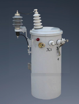
Global energy mandates strictly regulate core efficiency. The US Department of Energy (DOE 2016) and the EU EcoDesign Directive set maximum allowable loss thresholds. IEC 60076 standards provide the testing framework for verifying these losses. Non-compliant equipment faces import bans and heavy fines.
Evaluate the guaranteed loss values provided by the manufacturer. Scrutinize both load losses (copper losses) and no-load losses (iron losses). Load losses scale with the square of the current. No-load losses remain constant as long as the unit stays energized. Request a certified test report demonstrating compliance with local efficiency mandates before issuing a purchase order.
Winding material directly affects physical size, weight, and conductivity. Copper offers superior electrical conductivity. Copper windings result in a more compact core and lower overall volume. They handle short-circuit mechanical stresses exceptionally well. Aluminum windings cost less and weigh less. However, aluminum possesses lower conductivity. An aluminum-wound unit requires a larger core cross-section to achieve the same kVA rating.
Insulation class ratings define the maximum allowable temperature rise. Class A insulation supports a 55°C rise. Class B supports an 80°C rise. Class F and Class H support 115°C and 150°C rises, respectively. High-temperature insulation systems extend the solid insulation life. They allow the unit to run hotter without degrading the dielectric paper. Match the insulation class to your expected ambient temperatures and overload profiles.
Effective thermal management prevents catastrophic insulation failure. The standard cooling mechanism for liquid-filled units is ONAN (Oil Natural Air Natural). The oil circulates via natural convection. Heat transfers to the tank walls and external radiators. Ambient air cools the radiators.
Assess the unit's ability to handle temporary overloads. Industrial motors draw massive starting currents. The thermal inertia of the oil allows liquid-filled units to absorb these short-term spikes. Solid insulation degrades rapidly if temperatures exceed the design threshold. Every 10°C rise above the rated limit halves the lifespan of the cellulose paper. Specify a unit with adequate thermal margins if your load profile includes frequent, heavy motor starts.
Modern industrial distribution networks demand real-time visibility. Equip your units with smart sensors. These sensors track top oil temperature, internal tank pressure, and load parameters. Sudden pressure relays detect internal arcing instantly. They trip the primary breaker before the tank ruptures.
Integrate these sensors with your facility's SCADA system. Modern SCADA integration utilizes standard industrial protocols like Modbus TCP or DNP3. These protocols allow the condition monitoring sensors to communicate directly with the central control room. Set up automated alarm thresholds for top oil temperature and winding temperature. If the oil temperature exceeds 90°C, the system should trigger a warning. If it hits 105°C, the system must initiate an automated load-shedding sequence or trip the breaker to save the insulation. Remote industrial sites benefit massively from this connectivity. Operators monitor the health of isolated pumping stations from a central control room. Data analytics predict failure modes before they cause unplanned downtime.
Sourcing reliable equipment requires rigorous digital vetting. Do not rely solely on marketing brochures. Utilize structured online research to verify PDF technical datasheets. Cross-reference stated specifications against global certification databases. A reputable single phase transformer manufacturer publishes comprehensive technical data.
Validate the manufacturer's digital footprint. Look for historical performance data and independent third-party audit reports. KEMA, ASTA, or UL certifications prove that the design passed destructive testing. Misrepresented specifications plague the industrial equipment market. Verify the physical address of the manufacturing facility using satellite imagery. Check for active ISO 9001 and ISO 14001 registrations.
Never bypass the Factory Acceptance Test (FAT). The FAT proves the unit meets your exact specifications before it leaves the facility. Mandatory routine tests include winding resistance measurements and voltage ratio checks. Technicians must verify the impedance voltage and conduct rigorous dielectric tests. Applied voltage tests check the major insulation. Induced voltage tests check the turn-to-turn insulation.
Test Category | Specific Test | Purpose |
|---|---|---|
Routine (Every Unit) | Winding Resistance | Verifies manufacturing consistency and detects loose internal connections. |
Routine (Every Unit) | Dielectric Withstand | Ensures the insulation system can handle standard operating voltages without breakdown. |
Type (Design Validation) | Temperature Rise | Confirms the cooling system maintains temperatures below the specified insulation class limit. |
Special (On Request) | Lightning Impulse | Simulates high-voltage transients to verify the structural integrity of the insulation. |
Request type tests for new or custom designs. Lightning impulse tests simulate severe voltage transients. Short-circuit withstand capability tests prove the mechanical integrity of the core and coils. Establish a Dissolved Gas Analysis (DGA) baseline during the FAT. This baseline provides a reference point for future maintenance sampling.
Supply chain bottlenecks derail industrial projects. Assess the manufacturer's sourcing for critical raw materials. High-grade Cold Rolled Grain Oriented (CRGO) steel dictates core efficiency. Ask the vendor to identify their CRGO steel suppliers. Traceability ensures you receive the low-loss materials you paid for.
Evaluate production capacity realistically. Compare their proposed delivery schedules against your project timelines. Ask about their inventory of raw copper and dielectric fluids. A manufacturer with robust domestic supply chains navigates global shipping disruptions better than one reliant entirely on imported components. Build penalty clauses for late delivery into the procurement contract.
A strong warranty indicates manufacturer confidence. Analyze the fine print of the warranty coverage. Does it cover the cost of removal, shipping, and reinstallation? Many basic warranties only cover replacement parts. The labor and logistics of swapping a failed unit often exceed the cost of the hardware itself.
Investigate the availability of technical support. Ensure the manufacturer maintains a localized service network. You need rapid access to replacement bushings, gaskets, and tap changer components. Downtime costs thousands of dollars per hour in an industrial setting. Reliable post-installation support mitigates this financial risk.
The lowest-bidder procurement strategy often fails in power distribution. Upfront capital expenditure represents only a fraction of the total financial commitment. Operational expenditure accumulates over decades of continuous use. High-efficiency models carry a premium purchase price. However, they consume significantly less power during idle periods.
Calculate the payback period for high-efficiency models before making a decision. You will often find that the energy savings offset the initial premium within the first three to five years of operation. After the payback period, the reduced energy consumption translates directly into bottom-line savings for your facility.
No-load losses occur 24 hours a day, 365 days a year. The core remains magnetized regardless of the downstream load. You must monetize these core losses based on your local utility rates to understand their true financial impact.
Use a formulaic approach to evaluate competing bids. Multiply the guaranteed no-load loss in kilowatts by 8,760 hours per year. Multiply that figure by your industrial electricity rate. Project this annual cost over a 20-year lifespan. You will quickly see how continuous energization amplifies the financial impact of inefficient core designs. A cheaper unit with high iron losses will cost you substantially more over its operational life.
Improper commissioning destroys equipment instantly. Manage high inrush currents during initial energization. When you close the primary breaker, the core magnetizes rapidly. This draws an inrush current up to 10 times the full-load rating. This current spike can cause nuisance tripping of upstream protective relays. Adjust relay time-current curves to ride through this brief transient.
When landing the primary and secondary cables, ensure the conduit layout does not transfer mechanical stress to the bushings. Use flexible braided jumpers if the installation sits in a high-vibration environment. Verify the tap changer setting matches the actual grid voltage before closing the primary breaker. Operating a unit on the wrong tap setting forces the core into saturation, generating excessive heat and harmonic distortion.
Ensure proper grounding and bonding. The tank must connect solidly to the facility grounding grid. Target a ground resistance of less than 5 ohms. Proper grounding mitigates transient overvoltages from lightning strikes or switching surges. It provides a safe path for fault currents, protecting both personnel and downstream machinery. Verify all bushing connections with a calibrated torque wrench. Loose connections create high-resistance hot spots that melt terminal lugs.
Neglecting routine maintenance guarantees premature failure. Establish a baseline for predictive maintenance immediately after energization. Implement protocols for annual oil sampling. Test the dielectric strength to ensure no moisture ingress has occurred. Perform a Dissolved Gas Analysis (DGA) to detect incipient faults. When analyzing DGA results, look for specific fault gas signatures. High levels of hydrogen indicate partial discharge in the oil. Elevated ethylene points to severe oil overheating, often above 700°C. Acetylene is the most critical gas; its presence almost always confirms active arcing within the tank. If you detect acetylene, take the unit offline immediately for internal inspection.
Schedule routine infrared thermography inspections. Conduct infrared thermography during peak load conditions. A cold unit will not reveal high-resistance connections. Scan the primary and secondary bushings, looking for temperature differentials greater than 5°C between phases or connections. A hot spot on a terminal lug usually indicates a loose mechanical connection or oxidized mating surfaces. Schedule a brief outage to clean the contacts, apply conductive paste, and retorque the hardware to manufacturer specifications. Check the silica gel breathers on liquid-filled units. Replace the gel when it changes color from blue to pink, indicating moisture saturation. Keep the cooling radiators free of dust, debris, and industrial residue to maintain optimal ONAN cooling efficiency.
Selecting the right equipment dictates the reliability of your entire industrial power network. You must balance initial capital constraints with rigorous efficiency standards to ensure long-term viability. Advanced architectures provide a verifiable edge in reducing lifecycle operational costs and minimizing acoustic noise. Procurement teams must prioritize vendors that offer transparent testing documentation and utilize high-grade materials.
Follow these actionable steps to secure the optimal unit for your facility:
Conduct a comprehensive load profile study to determine exact kVA requirements and harmonic mitigation needs.
Define all environmental and spatial constraints, including NEMA ratings, altitude derating, and footprint limitations.
Request detailed technical data sheets (TDS) and certified loss test reports from a minimum of three vetted manufacturers.
Mandate a comprehensive Factory Acceptance Test (FAT) and review the baseline DGA results before accepting delivery.
Establish a proactive maintenance schedule utilizing infrared thermography and annual dielectric fluid sampling.
A: A single phase distribution transformer steps down voltage for localized end-user loads, typically operating below 35 kV. A power transformer handles massive bulk energy transfer across transmission networks, operating at much higher voltages and capacities. Distribution units prioritize low no-load losses due to continuous energization.
A: Calculate the total continuous load in kVA and add the peak starting demand of heavy motors. Apply a diversity factor based on simultaneous equipment usage. Finally, add a 20% margin for future capacity expansion. Avoid excessive over-sizing to minimize continuous no-load iron losses.
A: The D11-M(R) utilizes a three-dimensional continuous rolled core. This eliminates air gaps found in stacked cores, drastically reducing magnetic reluctance. It lowers excitation current by up to 70%, decreases no-load losses by roughly 30%, and reduces operational noise by 10 to 15 decibels.
A: Cross-reference their digital datasheets with global certification databases like KEMA or UL. Verify their physical manufacturing facility via satellite imagery. Look for published Factory Acceptance Test (FAT) sample reports, ISO 9001/14001 registrations, and independent third-party audit documentation.
A: Yes. You can connect a single-phase unit across two phases of a three-phase system or between one phase and the neutral. This is common for supplying localized single-phase loads like lighting or small motors within a broader three-phase facility.
A: An industrial-grade unit typically lasts 20 to 30 years under normal operating conditions. Lifespan depends heavily on thermal management. Operating continuously above the rated insulation temperature halves the life of the cellulose paper for every 10°C increase.
A: Copper offers superior electrical conductivity, resulting in a more compact core, smaller footprint, and better short-circuit mechanical strength. Aluminum costs less and weighs less but requires a larger core cross-section to achieve the same efficiency and kVA rating.

