


Views: 0 Author: Site Editor Publish Time: 2026-08-28 Origin: Site


The fundamental physics of voltage step-up and step-down remain constant across all electrical power networks. Yet, selecting the precise configuration for your facility directly impacts physical footprint, electrical efficiency, and long-term operational viability. This choice extends far beyond basic voltage conversion. Facility managers, procurement specialists, and electrical engineers face mounting pressure to balance strict safety compliance with optimal energy performance. You need to know exactly how these systems operate at a fundamental level before making a capital investment.
Understanding core mechanics bridges the crucial gap between theoretical physics and practical procurement. It dictates why certain designs thrive in harsh environments while others pose significant fire risks indoors. In this comprehensive guide, you will explore the essential working principles of multiphase power induction. We will decode flux cancellation, evaluate specialized core constructions, and guide you through matching modern high-efficiency units to your specific commercial or industrial load requirements.
A 3 phase transformer operates on Faraday’s Law of Electromagnetic Induction, utilizing a 120-degree phase shift to deliver continuous, efficient power while requiring less core material than three single-phase units.
Understanding the magnetic flux distribution helps explain why modern designs prioritize specific core materials and winding configurations to reduce energy loss.
For indoor or high-risk environments, a three phase dry type transformer or cast resin three phase transformer is typically required to meet strict fire and safety compliance standards.
High-efficiency standards, such as those met by the SCB14 three phase transformer, are critical benchmarks for evaluating Total Cost of Ownership (TCO) over a 20+ year lifecycle.
To grasp the operational advantages of a modern distribution network, we must first review the basic physics. The system relies entirely on electromagnetic induction. When an alternating current (AC) flows through the primary copper or aluminum windings, it generates a continuously varying magnetic field. This magnetic flux travels through a highly permeable steel core. As this moving magnetic field intersects the secondary windings, it induces a corresponding voltage. This allows us to step voltage up or down based on the exact ratio of wire turns between the primary and secondary coils.
However, the true engineering marvel lies in the 120-degree phase shift. In a single-phase system, voltage drops to zero twice per cycle. This can cause brief mechanical vibrations and slight power inconsistencies in large rotating machinery. A 3 phase transformer utilizes three distinct alternating currents operating simultaneously. Engineers stagger these phases precisely 120 electrical degrees apart. When phase A begins dropping toward zero, phase B or phase C is already peaking. The overall power delivery never drops to zero. You achieve remarkably smooth, continuous energy transfer.
This phase synchronization unlocks a massive physical advantage known as core flux cancellation. In a perfectly balanced three-phase system, the sum of the magnetic flux from all three phases equals exactly zero at any given millisecond. Because the magnetic fields effectively cancel each other out during their return path, engineers can safely eliminate the heavy, bulky central return leg required in single-phase core assemblies.
The bottom-line benefit is substantial. A single integrated unit requires significantly less structural steel and conductive material than three separate single-phase transformers wired together in a bank. You secure a lighter unit with a drastically smaller physical footprint. Furthermore, manufacturing one integrated housing reduces overall production expenses. This mechanical efficiency directly translates into easier shipping logistics, simpler rigging during facility installation, and tighter electrical room layouts.
Understanding the internal magnetic physics is only half the battle. You must perfectly match the external construction to your facility's environmental realities. Traditional liquid-filled units utilize mineral oil as both a dielectric insulator and a cooling agent. While excellent for outdoor utility substations, they pose severe flammability risks. Installing oil-filled tanks indoors generally requires constructing expensive, fire-rated concrete vaults and secondary fluid containment basins.
Most commercial and institutional facilities bypass these hazards by deploying a three phase dry type transformer. Rather than relying on combustible fluids, these units utilize ambient air as the primary cooling medium and dielectric insulator. Engineers heavily favor standard air-cooled dry types for high-rise office buildings, shopping centers, and underground mass transit stations. In these applications, eliminating fire risk and environmental contamination stands as the primary metric for project success.
However, standard ventilated dry-type models do have limitations. Because they rely on ambient air circulation, the internal coils remain somewhat exposed. High humidity, airborne metallic dust, and corrosive chemical vapors can degrade standard winding insulation over time. When specifying equipment for harsh industrial plants, paper mills, or coastal marine environments, standard air-cooling often falls short.
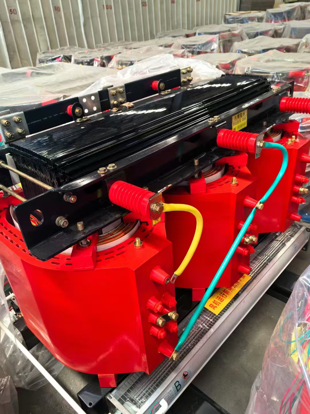
This is precisely where a cast resin three phase transformer becomes necessary. During manufacturing, the internal copper or aluminum windings are placed inside a vacuum chamber and completely encapsulated in high-grade epoxy resin. This solid resin block cures into an impenetrable protective shell. It actively locks out moisture, preventing insulation breakdown even in 100% humidity environments. Additionally, the hardened resin provides exceptional mechanical rigidity. During a severe short-circuit event, electromagnetic forces try to violently repel the wire coils. The solid resin prevents this dangerous movement, granting the unit vastly superior short-circuit withstand capabilities compared to standard air-cooled models.
Energy grids worldwide are tightening their efficiency mandates. Facility managers can no longer afford to install poorly optimized equipment. The SCB14 three phase transformer represents a modern, stringent benchmark for energy conservation in dry-type applications. It integrates advanced material science to systematically eliminate wasted electricity.
To evaluate its performance, we must dissect the two primary categories of electrical loss. First, we examine no-load losses, commonly called core losses. These occur constantly, 24 hours a day, regardless of whether the building is drawing heavy power or sitting empty. As the AC current alternates, it forces the steel core to repeatedly magnetize and demagnetize. This friction creates hysteresis and eddy current losses. The SCB14 standard addresses this by utilizing ultra-high-permeability, cold-rolled grain-oriented silicon steel. These premium laminations offer far less magnetic resistance, drastically cutting down continuous energy waste.
Second, we must account for load losses, also known as copper losses. These scale dynamically based on facility demand. As electrical current travels through the primary and secondary windings, natural conductor resistance generates heat. SCB14 models employ optimized winding geometries, highly refined conductor materials, and superior jointing techniques to minimize electrical resistance pathways.
The resulting operational savings are profound. Because these advanced units run highly efficiently, they waste very little energy as ambient heat. Consequently, your electrical room requires significantly less active HVAC cooling. Over a standard 20-to-30-year operational lifecycle, the compounded savings from reduced electrical waste and lowered cooling demands easily offset the higher initial procurement costs of an SCB14 unit.
Table: Standard vs. Advanced High-Efficiency Core Properties
Performance Metric | Standard Legacy Transformer | SCB14 Advanced Standard |
|---|---|---|
Core Material | Standard Silicon Steel | High-Permeability Grain-Oriented Steel |
No-Load (Core) Losses | Baseline / Average | Significantly Reduced (Up to 20-30% lower) |
Operating Temperature Rise | Higher heat dissipation | Lower heat output, easing HVAC loads |
Lifecycle Energy Savings | Minimal | High (Optimized for long-term efficiency) |
Moving from technical principles to active procurement requires a structured evaluation framework. You cannot select a unit based on capacity alone. Electrical engineers must analyze several overlapping variables to ensure safety, reliability, and code compliance. Keep the following dimensions at the forefront of your specification process.
Scalability and Load Profiling: Sizing the equipment correctly is paramount. You must calculate the current peak facility load while factoring in anticipated future expansions. Severe under-sizing leads to chronic overheating and accelerated insulation failure. Conversely, excessive over-sizing forces the unit to operate far below its optimal efficiency curve, needlessly inflating your utility bills.
Vector Group Selection: The vector group defines exactly how the primary and secondary coils are connected (e.g., Delta or Star configurations) and denotes the specific phase shift angle. A common industry standard is Dyn11 (Delta primary, Star secondary, with a 30-degree phase advance). Specifying the exact vector group is absolutely non-negotiable if you intend to operate multiple units in parallel on the same grid. It also dictates how effectively the system can ground unbalanced, non-linear loads.
Cooling and Ventilation Strategies (AF vs. AN): You must decide between Air Natural (AN) and Air Forced (AF) cooling methods. AN relies entirely on passive thermal convection. Hot air rises and exits the enclosure, drawing cooler air in from the bottom. AF incorporates integrated thermostatic cooling fans. When temperatures peak during heavy loads, fans activate to force air across the coils. An AF configuration can safely boost continuous capacity by up to 33%. Select AF if your electrical room experiences high ambient temperatures or sudden, aggressive load spikes.
Compliance and Certifications: Equipment must strictly align with regional safety codes. Depending on your jurisdiction, require verifiable documentation that the unit meets IEC (International Electrotechnical Commission) or IEEE standards. These standards dictate rigorous factory testing for dielectric strength, impulse voltage withstand, and temperature rise limits. Missing these certifications will likely void commercial property insurance policies and fail municipal fire inspections.
Even the most perfectly specified equipment carries inherent implementation risks. Facility teams must proactively manage these challenges during installation and daily operation. The first major hurdle is inrush current management. When you initially energize a large magnetic core, it requires a massive, instantaneous surge of electricity to establish the internal magnetic field. This transient inrush can briefly spike up to ten times the unit’s normal full-load current.
While this surge lasts only a few milliseconds, it routinely causes severe nuisance tripping in upstream circuit breakers. Engineers must conduct a precise coordination study. You need to adjust the upstream breaker’s time-current curve to briefly ignore this initial magnetic surge without compromising fast-acting short-circuit protection.
Harmonic distortion presents a continuous, modern operational threat. Legacy facilities mostly powered linear loads like incandescent lighting and simple induction motors. Today’s commercial buildings are packed with non-linear electronics. LED lighting drivers, server racks, and variable frequency drives (VFDs) pull electricity in rapid, non-sinusoidal pulses. This severely distorts the facility's electrical waveform.
Harmonics force standard winding configurations to operate highly inefficiently, causing massive internal heat buildup. If a standard unit powers heavy IT or VFD loads, the insulation will bake and fail prematurely. Best practices dictate conducting a load analysis. If harmonics are present, you must specify a K-factor rated unit. These specialized models feature oversized neutral conductors and reorganized winding layouts specifically engineered to survive intense harmonic heating.
Finally, we must address vibration and acoustic noise. We established earlier that the alternating magnetic field forces the steel laminations in the core to rapidly expand and contract. This physical shifting is called magnetostriction. It produces the distinct low-frequency, 120-hertz hum common in electrical rooms. Because dry-type units lack liquid to dampen this sound, the noise can travel aggressively through building structures. If you install the equipment near occupied office spaces or hospital wards, implement strict acoustic isolation. Utilize flexible braided conduits for all electrical connections and place thick neoprene anti-vibration isolation pads beneath the chassis footprint.
The foundational working principles of multiphase induction remain highly elegant and mathematically straightforward. The synchronized 120-degree phase shift eliminates the need for massive return cores, delivering smoother power in a dramatically condensed footprint. However, how you apply that underlying physics dictates your ultimate success. The physical construction, core material, and cooling strategy directly control the unit’s long-term electrical efficiency, ambient noise levels, and fire safety ratings.
Your next steps require precise operational mapping. Audit your facility’s environmental realities first. Determine if airborne dust, corrosive moisture, or indoor fire regulations mandate encapsulated resin over standard ventilated designs. Then, chart your anticipated harmonic load profiles to avoid premature insulation burnout. By prioritizing advanced efficiency benchmarks over outdated legacy designs, you ensure a resilient, high-performing electrical backbone capable of supporting modern commercial demands for decades to come.
A: The primary advantage is core flux cancellation. Because the magnetic fields of the three synchronized phases naturally balance to zero, engineers can eliminate the central return leg of the core. This reduces total core material, drastically shrinks the physical footprint, lowers overall weight, and reduces total installation costs compared to banking three separate units.
A: You should specify cast resin designs for harsh environments where standard air cooling would expose coils to damage. They are essential in areas with extreme moisture, heavy metallic dust, or corrosive chemical vapors. The solid epoxy encapsulation protects the windings and provides exceptional mechanical strength against violent short-circuit forces.
A: The SCB14 standard significantly lowers operational expenses by drastically reducing no-load (core) and load (copper) electrical losses. It utilizes premium grain-oriented silicon steel and optimized windings. This high efficiency translates to less wasted electricity and generates significantly less ambient heat, thereby slashing the cooling loads on electrical room HVAC systems.
A: While they avoid the fluid sampling required by oil-filled units, they still require strict routine maintenance. Best practices include performing annual infrared thermal imaging to detect loose, overheating joints. Technicians must routinely check torque on all electrical connections and vacuum internal cooling channels to ensure accumulated dust does not block critical airflow.

