


Views: 0 Author: Site Editor Publish Time: 2026-08-30 Origin: Site


Interpreting a 3 phase transformer wiring diagram incorrectly carries massive operational stakes. Misinterpreting these electrical schematics quickly leads to phase imbalances, destructive circulating currents, or even catastrophic equipment failure. For engineers and facility managers, selecting the right wiring setup goes beyond a technical formality. You must carefully evaluate Wye and Delta combinations. This crucial choice dictates your entire system grounding approach. It also governs harmonic mitigation capabilities and long-term facility scalability.
Getting this configuration wrong risks severe power quality issues across your entire electrical network. This guide dissects standard wiring diagrams clearly. We map these exact configurations to medium-voltage applications. You will learn how to read vector groups and terminal markings accurately. By the end, we provide a solid framework for specifying the proper configuration for your specific site requirements.
Configuration Dictates Application: Delta-Wye (Dyn) is the industry standard for commercial and industrial step-down applications due to its ability to serve both three-phase and single-phase loads.
Vector Groups Matter: Understanding standard phase shifts (e.g., Dyn11 vs. Dyn1) is critical when paralleling transformers to prevent severe short-circuit conditions.
Voltage Scaling Requires Precision: Medium-voltage variants (10kV, 20kV, and 35kV) require specific termination and grounding clearances detailed in manufacturer wiring diagrams.
Compliance & Testing: Always verify that proposed wiring diagrams align with site-specific IEEE or IEC standards before approving for procurement.
Electrical system designers categorize solutions based on precise load requirements and existing facility infrastructure. Selecting between primary and secondary winding connections fundamentally alters how the system handles voltage levels, grounding, and fault currents. We can break down the four primary configurations typically found on manufacturer wiring diagrams.
This configuration connects both the primary and secondary windings in a closed loop. Engineers often specify this setup for heavy industrial environments. It strictly serves three-phase motor loads without requiring a neutral wire.
Best for: Heavy industrial environments with strictly three-phase motor loads.
Evaluation factor: It offers exceptional reliability. If one phase fails, the unit can operate in an "open-delta" (or V-connection) at reduced capacity. However, it completely lacks a neutral point for single-phase loads. This limits flexibility in mixed-use facilities.
You will see this setup most frequently in modern distribution networks. The primary uses a Delta connection, while the secondary employs a Wye connection to provide a neutral point.
Best for: Commercial and industrial distribution.
Evaluation factor: It traps zero-sequence harmonics effectively in the primary delta winding. This prevents harmonic currents from flowing back into the utility grid. Furthermore, it provides a highly stable neutral on the secondary side. You can safely power mixed loads, combining three-phase machinery and single-phase lighting.
This symmetric configuration connects both sides in a star pattern. Wiring diagrams for this setup often feature extensive grounding details.
Best for: High-voltage transmission networks where grounding both the primary and secondary sides is strictly required.
Evaluation factor: It is highly susceptible to third-harmonic distortion unless equipped with a tertiary delta winding. Without proper stabilization, you risk severe communication interference and dangerous neutral voltage shifts if improperly grounded.
Typically utilized in reverse to the Delta-Wye, this configuration handles substantial voltage increases efficiently.
Best for: Step-up applications, such as renewable energy substations feeding power back into the utility grid.
Evaluation factor: It provides a reliable grounding point on the high-voltage primary side. This ensures strong system stability for grid interconnection while isolating secondary faults.
Configuration | Primary Use Case | Neutral Availability | Harmonic Mitigation |
|---|---|---|---|
Delta-Delta (Δ-Δ) | Heavy industrial motors | None | Moderate |
Delta-Wye (Δ-Y) | Commercial distribution | Yes (Secondary) | Excellent (Traps zero-sequence) |
Wye-Wye (Y-Y) | High-voltage transmission | Yes (Both sides) | Poor (Needs tertiary winding) |
Wye-Delta (Y-Δ) | Renewable step-up | Yes (Primary) | Good |
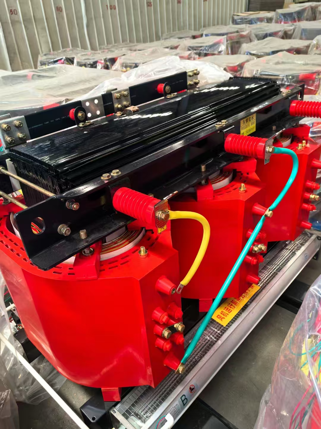
Implementation reality dictates extreme caution as you move into medium-voltage territories. Higher voltage classes demand much stricter adherence to diagrammed clearances. Insulation levels, specifically Basic Impulse Insulation Levels (BIL), become critical parameters. Wiring diagrams must explicitly show termination styles to prevent arc flashes or phase-to-ground faults.
You will frequently encounter these systems in regional industrial parks and large commercial complexes. Operating at this voltage requires precise protection coordination.
When specifying a 10kV three phase transformer, your specification focus must shift to termination logistics. The wiring diagram must clearly indicate primary surge arrester placements. You also need to verify preferred cable entry points. Vault constraints often dictate whether you need top-entry or bottom-entry cable configurations. Failing to specify this on the diagram leads to expensive installation delays.
These systems represent the standard for heavy commercial campuses or grid-tied renewable projects. They bridge the gap between regional distribution and heavy industrial utilization.
Integrating a 20kV three phase transformer demands forward-thinking engineering. Focus heavily on dual-voltage primary wiring diagrams. Many modern utility grids undergo periodic voltage upgrades. If you anticipate a future switch from 10kV to 20kV, a dual-voltage schematic allows contractors to simply switch a series-parallel terminal board. This avoids replacing the entire unit down the line.
This voltage class is heavily utilized in massive industrial operations, mining sites, and primary utility substations. The electrical stress at this level leaves zero room for misinterpretation.
Deploying a 35kV three phase transformer introduces extreme high-stress insulation requirements. Diagrams must specify exact bushing configurations and robust ground pad locations. Furthermore, the schematics must detail adequate electrostatic shielding. This shielding mitigates corona discharge risks, which can quickly degrade insulation and cause catastrophic faults if overlooked.
Merely reading the connections is insufficient. You must translate the diagrammatic symbols into real-world operational outcomes. Engineers evaluate schematics based on vector groups, grounding limits, and voltage regulation mechanisms.
Vector Group Compatibility (Phase Displacement): Manufacturers use a "clock face" nomenclature on wiring diagrams. You will see terms like Dyn1 or YNd11. The letters indicate the winding types (Delta or Wye). The number indicates the phase shift between the primary and secondary voltages. For example, an "11" denotes a 30-degree phase lead, while a "1" denotes a 30-degree lag. Paralleling units requires identical vector groups. Mismatches instantly cause destructive circulating currents that trip breakers and damage windings.
Grounding and Neutral Sizing: You must evaluate diagrams for neutral terminal sizing. Facilities often feature high non-linear loads. Modern environments heavily utilize LED lighting arrays, Variable Frequency Drives (VFDs), and switching power supplies. These loads generate massive triplen harmonics (3rd, 9th, 15th) that accumulate on the neutral wire. Never assume a standard neutral is sufficient for heavy IT or data center loads. Instead, specify K-rated units featuring at least 200% upsized neutrals to safely dissipate these harmonic currents.
Tap Changer Integration: Grid voltage rarely remains perfectly static. Assess how tap changers are represented on the wiring diagram. Most standard units feature an Off-Circuit Tap Changer (OCTC). You must physically de-energize the unit to adjust voltage ratios. However, volatile local grids may require an On-Load Tap Changer (OLTC). The diagram must clearly show OLTC control wiring and motor drive mechanisms to ensure proper integration with facility SCADA systems.
Even a perfectly designed wiring diagram poses severe risks if installation teams misinterpret the standards. Compliance requires strict attention to regional marking rules and physical testing protocols.
Global supply chains mix different engineering standards. IEC standards typically label primary terminals as U, V, and W. In contrast, NEMA/ANSI standards label primary terminals as H1, H2, and H3, and secondary terminals as X1, X2, and X3. Mixing these up is a common yet disastrous mistake. Ensure cross-border procurement documentation clearly specifies which standard the wiring diagram follows. This simple risk mitigation prevents severe installation errors by local electrical contractors.
Wiring diagrams dictate specific phase rotation sequences. A reversed phase rotation during installation causes all three-phase motors downstream to run backward. This can instantly destroy pumps, compressors, and conveyor systems. As a best practice, always mandate extensive Factory Acceptance Testing (FAT). The FAT must include vector group validation and polarity verification. Review these test results directly against the approved wiring schematic before authorizing shipment.
Wiring schematics display ideal, perfectly balanced conditions. Real-world facilities rarely operate this way. Address the physical limitations shown in the documentation regarding phase unbalance. Unbalanced secondary loads physically reflect back to the primary windings. This unbalance generates negative sequence currents. If not properly accounted for in the system protection design, these currents overheat the iron core and trigger ANSI 46 protective relay tripping. Verify your unbalance tolerance limits with the manufacturer directly.
Selecting the right vendor is just as critical as interpreting the schematic. You need an engineering partner, not just a hardware supplier. Use these criteria to evaluate potential manufacturers based on their documentation capabilities.
Customization of Schematics: Determine if the vendor provides site-specific, as-built wiring diagrams. Some merely offer generic catalog cut-sheets. You need detailed drawings reflecting your exact termination points and accessory locations.
Engineering Support: Evaluate their willingness to consult on complex parallel integrations. Do they understand specialized vector groups? Will they help coordinate your protective relay settings with their diagram parameters?
Evidence of Reliability: Look for manufacturers who transparently provide comprehensive routine test reports. They should map IEEE or IEC routine tests directly back to the nodes on their wiring schematics. This proves their theoretical diagrams match the physical build.
Next Step Action: Gather your facility single-line diagram (SLD) and expected load profile. Request preliminary wiring configurations and dimensional footprint drawings from shortlisted vendors for a thorough engineering review.
Interpreting a 3-phase wiring diagram correctly is the absolute foundation of achieving a safe, compliant, and highly scalable electrical infrastructure. These schematics do much more than show wire connections. They dictate harmonic management, phase synchronization, and critical safety grounding methodologies.
Remember that increasing voltage classes dictate fundamentally different structural requirements. Moving from low voltage up to 35kV means terminal clearances, shielding, and testing protocols become significantly stricter. An error on paper translates to massive physical risk in the field.
Always encourage your procurement and engineering buyers to engage directly with technical sales teams. Bring your single-line diagrams to the table early. Verify configuration compatibility, load balance tolerances, and vector groups completely before ever requesting a formal manufacturing quote.
A: Base your choice strictly on your load types. A Wye secondary provides a stable neutral point. This allows you to safely serve a mix of single-phase loads (like lighting or computers) and three-phase machinery simultaneously. Choose a Delta secondary only if you are feeding dedicated, balanced three-phase motor loads that do not require a neutral wire.
A: This is standard IEC vector group notation. The capital "D" means the primary is Delta-connected. The lowercase "y" means the secondary is Wye-connected. The "n" indicates the neutral point is brought out for connection. Finally, the "11" means the secondary voltage leads the primary voltage by exactly 30 degrees (like 11 o'clock on a clock face).
A: Yes, it is physically feasible for specific heavy industrial uses. However, a pure Delta-Delta setup lacks a ground reference. To ensure system safety and meet modern protection standards at 35kV, you will likely need to install a separate grounding transformer (such as a zig-zag configuration) to detect and clear phase-to-ground faults.
A: The tertiary winding exists specifically for harmonic mitigation and stabilization. Wye-Wye configurations are inherently unstable when handling unbalanced loads and they severely amplify third-harmonic currents. The closed Delta tertiary winding acts as a trap. It forces these harmful third-harmonic currents to circulate harmlessly within the loop, thereby stabilizing the neutral point.

