


Views: 0 Author: Site Editor Publish Time: 2026-09-26 Origin: Site


Wiring a step up transformer requires absolute precision and careful planning. A single misinterpretation of a wiring diagram can cause severe systemic failures. Electrical professionals face immense pressure to execute these connections flawlessly every time.
In industrial and commercial settings, the operational stakes remain incredibly high. Minor wiring errors often lead to catastrophic arc flashes. They can also trigger extensive equipment damage or deeply compromise facility power quality. System safety and long-term equipment longevity depend entirely on accurate installation practices.
Successful implementation relies on strictly following the manufacturer’s nameplate. Installers must also adhere to IEEE and NEC standards. Precise terminal mapping is critical for safe operation. This guide breaks down schematic interpretation, essential pre-installation sizing, and step-by-step connection protocols. You will learn how to mitigate risks and ensure perfectly compliant electrical integration.
Terminal Reversal is Standard: In a step up transformer, the power source connects to the low-voltage terminals (X1, X2, X3) and the load connects to the high-voltage terminals (H1, H2, H3).
Grounding is Non-Negotiable: Proper system and equipment grounding must be established before energizing to mitigate transient overvoltages.
Nameplate Dictates Implementation: Wiring diagrams are specific to winding configurations (Delta-Wye, Delta-Delta); generic schematics cannot override manufacturer specifications.
Verify Before Energizing: Insulation resistance (Megger) and turns ratio testing are mandatory pre-commissioning steps.
Electrical engineers rely on universal NEMA and ANSI standards to map connections. Under these guidelines, the letter 'H' always denotes high voltage. The letter 'X' always denotes low voltage. You must pay close attention to this naming convention. In standard step-down applications, power enters the H terminals. However, step-up applications reverse this logic. Your primary power source connects to the 'X' terminals. Your higher-voltage load connects to the 'H' terminals. Recognizing this intentional terminal reversal prevents catastrophic wiring mistakes.
You must evaluate Delta and Wye connections based on your specific facility needs. Wye connections provide a neutral point. This neutral allows you to serve single-phase loads easily. It also simplifies your system grounding strategy. Delta connections lack this neutral point. They typically serve dedicated three-phase motor loads. Your facility grounding requirements will dictate which winding configuration you select. You must match the transformer wiring diagram to these phase balancing needs exactly.
Characteristic | Delta Configuration | Wye Configuration |
|---|---|---|
Wiring Structure | Series loop connection (Triangle) | Common central point (Star) |
Neutral Wire | Not available | Present at the common center |
Phase Balancing | Tolerates slight imbalances well | Requires careful load balancing |
Primary Use Case | Heavy industrial motor loads | Mixed single and three-phase loads |
Wiring diagrams clearly indicate phase shifts through vector groups. A common example is Dyn11. This alphanumeric code tells you the primary is Delta (D). It indicates the secondary is Wye (y). It also shows the neutral is brought out (n). The '11' indicates a 30-degree phase shift leading. You must understand this displacement when paralleling transformers. If you ignore vector groups, you risk massive circulating currents when integrating new units into existing switchgear.
Generic schematics hold no authority on the job site. Procurement and engineering teams must validate everything against the physical nameplate. You need to check the percentage impedance (%Z). You must confirm the kVA rating. You also need to verify the tap changer settings. The physical wiring diagram on the nameplate overrides any generalized drawings. Failing to match your connections to the nameplate violates NEC guidelines and voids manufacturer warranties.
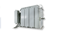
Accurate load profiling prevents you from over-specifying equipment. You must calculate your continuous load demands first. Next, you need to factor in peak inrush currents. Motors and compressors draw significant starting current. You must select a kVA rating capable of handling these transient spikes. Proper capacity planning ensures stable voltages without wasting capital on unnecessarily oversized units.
Selecting primary breakers and secondary fuses requires exact coordination. You face a specific challenge here. The low-voltage side experiences massive inrush currents during energization. Your primary breaker must allow this inrush without tripping prematurely. At the same time, it must protect against actual fault conditions. You should consult time-current curve charts to select the proper breaker trip settings for the X terminals.
Site readiness goes beyond floor space. You must assess enclosure types against your deployment realities. Indoor electrical rooms typically use NEMA 1 enclosures. Exposed outdoor substations demand NEMA 3R or NEMA 4X ratings. You must guarantee adequate ventilation around the unit. Blocked cooling vents will cause the unit to overheat rapidly. Always confirm your enclosure rating matches the environmental hazards present at your installation site.
Facility managers frequently ask if they can backfeed a standard step-down unit. We strongly advise against this practice. Reverse-wiring a step-down transformer introduces severe performance limitations. It often voids the original warranty. Backfeeding creates massive inrush currents on the low-voltage windings. These windings were not designed to act as primary inputs. Procuring a purpose-built unit guarantees NEC compliance and ensures long-term operational stability.
Evaluation Metric | Purpose-Built Step-Up Unit | Backfed Step-Down Unit |
|---|---|---|
Inrush Current Handling | Optimized for low-voltage side input | Can exceed standard breaker trip curves |
Voltage Tap Adjustments | Correctly placed on the primary input side | Placed on output, rendering them useless |
NEC Compliance | Fully compliant and certified | Requires specific exceptions and custom labeling |
Warranty Status | Fully supported by the manufacturer | Typically voided upon reverse energization |
You must establish baseline safety requirements before any physical connection begins. De-energize all incoming power feeds. Apply strict Lockout/Tagout (LOTO) procedures at the main breaker panel. Verify the absence of voltage using a properly calibrated multimeter. Never assume a circuit is dead. Strict adherence to LOTO protocols prevents fatal electrical shocks during the installation process.
Identify the X Terminals: Locate X1, X2, and X3 on the low-voltage side of the equipment.
Size the Conductors: Use properly sized cables. The low-voltage input requires significantly larger conductors to handle higher amperages.
Land the Cables: Connect your source cables to the X terminals.
Apply Proper Torque: Tighten all lugs to the exact torque specifications listed on the nameplate. Loose connections cause arcing and heat buildup.
Routing the high-voltage cables requires careful attention to physical separation. You must connect your load to the H1, H2, and H3 terminals. Maintain strict distance between your high-voltage output cables and the low-voltage input wiring. Crossing these cables can induce unwanted electrical noise. Always verify you have adequate insulation rated for the higher output voltage.
System grounding establishes a safe reference point for your electrical infrastructure. First, you must ground the metal chassis directly to the facility grounding electrode system. Next, if you use a Wye configuration, you must bond the neutral terminal (X0 or H0) properly. Grounding mitigates transient overvoltages during lightning strikes or line faults. Never skip this non-negotiable safety step.
Utility supply voltages often fluctuate. You can mitigate these supply fluctuations using the primary tap changer. First, measure your incoming source voltage accurately. Next, compare this reading to the nominal rating on the nameplate. Finally, adjust the primary taps to match your actual incoming voltage. This adjustment ensures you get the exact desired output voltage on the secondary side.
Industrial manufacturing and massive data centers require robust power distribution. Specifying a medium voltage step up transformer addresses these heavy demands. Implementation realities change significantly at medium voltages. You must account for greater arc flash boundaries. Your facility will also need specialized medium voltage switchgear. Personnel must wear appropriately rated arc flash suits when operating near these installations.
Renewable power systems rely heavily on voltage elevation. Solar inverters and wind turbine nacelles generate power at lower voltages. You typically need a 37kV 0.6kV step up transformer to elevate this generated power for grid transmission. The wiring topology here focuses on maximum efficiency. The low-voltage side connects directly to the inverter output. The high-voltage side ties into the collection grid. These units must withstand harsh outdoor environments and constant load fluctuations.
Medium voltage cables behave differently than standard low-voltage wiring. You cannot simply strip the insulation and bolt them to a lug. You must use specialized termination techniques to prevent insulation breakdown. Installers must build stress cones at every cable termination. These stress cones control the electric field concentration where the cable shield ends. Without proper shielding and stress control, the cable insulation will quickly degrade and fail.
Utility substations and heavy industrial plants operate on massive scales. When evaluating a 66kV step up transformer, you face intense logistical challenges. You must coordinate heavy crane rigging and specialized transport. The foundational concrete pads must support immense weight. Furthermore, grid-level units require extensive oil containment systems. You must comply with EPA spill prevention guidelines when installing oil-immersed transformers of this magnitude.
Large-scale transformers require active monitoring systems. You must wire auxiliary protection components into the broader facility management system. These include:
Buchholz Relays: Detect gas accumulation from internal faults in oil-filled units.
Winding Temperature Indicators: Trigger cooling fans or trip circuits if the coils overheat.
CTs and PTs: Current and Potential Transformers feed live data to your SCADA monitoring panels.
Properly integrating these relays prevents catastrophic failures. They allow operators to detect minor anomalies before they escalate into major explosions.
Choosing the right manufacturer is just as important as reading the wiring diagram. You should look for several key indicators during the decision stage. Request copies of their routine testing reports. Ensure they perform factory acceptance tests (FAT). Ask about custom tap configurations for your specific grid voltage. Finally, evaluate their lead times and post-installation support. A reliable vendor will provide dedicated engineering support during the commissioning phase.
Do not finalize a purchase order based on assumptions. We recommend scheduling a comprehensive engineering review immediately. Share your facility single-line diagrams with a certified electrical engineer. Have them verify your load calculations and short-circuit current ratings. Once the engineering review is complete, you can confidently issue a purchase order for a purpose-built unit.
Accurate wiring is the direct byproduct of rigorous pre-installation planning. You must commit to strict adherence to schematic details. The nameplate remains your ultimate authority on the job site. Never substitute generic wiring diagrams for manufacturer-specific instructions. Precision ensures both safety and system longevity.
We reiterate that investing in purpose-built step-up equipment ensures operational stability. Backfeeding step-down units introduces unnecessary risks and compliance issues. Protect your facility by utilizing properly engineered hardware. Verify your grounds, double-check your torque settings, and mandate pre-commissioning Megger tests.
If you face uncertainties, do not guess. Consult with certified electrical engineers regarding your specific applications. You should also contact a specialized manufacturer. Provide them with your site-specific single-line diagrams. They can guide you toward the safest, most efficient electrical integration possible.
A: While theoretically possible, we strongly advise against it. Backfeeding violates many manufacturer warranties and complicates NEC compliance. The low-voltage windings are not designed for massive initial inrush currents. Furthermore, your voltage taps will end up on the output side, rendering them useless for regulating incoming supply fluctuations.
A: You determine wire size by calculating the ampacity based on the unit's kVA rating and operating voltage. Because the X terminals handle low voltage, they draw significantly higher current. Therefore, the low-voltage side requires much larger conductors. Always consult the NEC ampacity tables to finalize your wire sizing.
A: You must perform several mandatory tests before throwing the breaker. Conduct a Megger test to verify insulation resistance. Perform basic continuity checks to ensure tight connections. Finally, execute a Transformer Turns Ratio (TTR) test. These steps confirm internal integrity and prevent explosive failures upon energization.
A: Delta configurations form a closed triangle loop, creating a three-wire ungrounded system. This design naturally lacks a central neutral point. It is highly effective for balancing dedicated three-phase motor loads. If your facility requires a neutral for single-phase loads, you must utilize a four-wire Wye configuration instead.

