


Views: 0 Author: Site Editor Publish Time: 2026-09-28 Origin: Site


Finding the exact capacity for your power distribution network is a strict engineering requirement. It heavily safeguards your capital and operational budgets. Many engineers rely on basic online calculators. They often ignore specific load profiles during this process. Forgetting motor inrush currents, power factor drops, or harmonic distortion creates massive operational risks. You might face dangerous equipment under-sizing. This directly causes severe overheating and rapid voltage drops. Conversely, you might face costly over-sizing. Over-sizing wastes upfront capital and increases continuous no-load losses. We need a more reliable approach. You must use a standardized, evidence-based method to calculate your exact load requirements. This guide gives you the necessary formulas and practical steps. You will learn how to translate raw numbers into a compliant, vendor-ready procurement specification. You will master the variables necessary to guarantee long-term performance.
Total load calculations must convert Real Power (kW) to Apparent Power (kVA) by factoring in the specific Power Factor (PF) of the facility’s equipment.
Motor start-up inrush currents require calculating continuous vs. non-continuous loads to prevent nuisance tripping and transformer thermal damage.
Environmental placement directly influences sizing and type selection, dictating whether an oil immersed step up transformer or a specialized outdoor pad-mounted unit is required.
Final procurement should base specifications on IEEE/IEC standards and NEC guidelines, not just baseline capacity formulas.
Selecting the wrong equipment capacity introduces severe operational threats. These threats impact both daily production and long-term facility safety. You must understand these risks before finalizing any electrical design.
Under-sizing limits your electrical infrastructure immediately. It creates a dangerous environment for your connected equipment. The primary risk is thermal overload. Heat destroys internal paper insulation rapidly. Accelerated insulation degradation drastically shortens equipment lifespan. You will experience unplanned downtime. The risk of catastrophic failure rises exponentially during peak production hours. Furthermore, an undersized unit cannot support future facility expansion. You will have to replace the entire unit if you add new loads later.
Many engineers intentionally oversize equipment to avoid thermal risks. This approach creates its own set of problems. Over-sizing requires unnecessary upfront capital expenditure. It also creates a continuous operational drain. Transformers consume power even when idling. Excessive core losses accumulate significantly over a 20-30 year lifespan. These no-load losses waste massive amounts of electricity. Additionally, a larger unit outputs higher fault currents. This often forces you to purchase oversized, expensive protective switchgear to handle potential short circuits.
You want to achieve the optimal "Goldilocks" zone. You must size the unit for your current peak loads first. Then, you add a data-backed safety margin. Industry best practices suggest a 20-25% expansion margin. This strategy aligns perfectly with NEC Article 450 requirements. It balances initial capital investment against long-term reliability and safety.
Equipment Sizing Risks Comparison
Sizing Error | Primary Risk | Secondary Impact | Long-term Consequence |
|---|---|---|---|
Under-Sizing | Thermal Overload | Insulation Degradation | Catastrophic Failure & Downtime |
Over-Sizing | High No-Load Losses | Excessive Core Heating | Wasted Operational Expenditure |
Optimal Sizing | Stable Operation | Proper Fault Currents | Maximized Equipment Lifespan |
You must move beyond generic rules of thumb. Exact mathematical modeling ensures system stability. Proper load calculation forms the foundation of any reliable electrical system.
Calculating the required capacity requires precise mathematical steps. You cannot simply guess the total load. We use specific formulas based on the phase configuration of your system. You must gather accurate voltage and amperage data from your equipment nameplates. Doing this prevents critical sizing errors.
Identify the operating voltage of your connected loads.
Determine the maximum current (Amps) drawn by these loads.
Identify the phase configuration (single-phase or three-phase).
Apply the correct capacity multiplier based on system type.
Single-phase loads are common in lighter commercial applications. The math here is straightforward. You multiply the load voltage by the load amps. Then, you divide the result by 1000. This converts basic Volt-Amperes (VA) into Kilovolt-Amperes (kVA).
Formula: kVA = (Load Voltage × Load Amps) / 1000
Industrial applications almost exclusively use three-phase power. Three-phase math introduces a specific constant. You must account for the square root of three (1.732). You multiply the voltage, amperage, and this constant together. Finally, you divide by 1000. This guarantees an accurate baseline when sizing your step up transformer for industrial loads.
Formula: kVA = (Load Voltage × Load Amps × 1.732) / 1000
Equipment nameplates often list power in Kilowatts (kW). You cannot use kW directly for sizing. Kilowatts represent real working power. Transformers must supply Apparent Power (kVA). Apparent power includes both working power and reactive power. You bridge this gap using the Power Factor (PF).
Formula: kVA = kW / Power Factor (PF)
Never assume a perfect 1.0 PF. This is a common and dangerous assumption. Industrial motor loads typically operate between 0.8 and 0.85 PF. Using a 1.0 multiplier will mathematically guarantee under-sizing. Always divide your total kW by the actual facility PF.
Basic formulas only calculate steady-state operations. Real-world electrical networks are highly dynamic. You must adjust your baseline capacity to handle sudden surges and waveform distortions. Ignoring these variables leads to erratic system behavior.
Electric motors demand massive energy during startup. This surge is known as the inrush current. You must address the difference between Locked Rotor Amps (LRA) and Full Load Amps (FLA). The LRA can be six to eight times higher than the FLA. This massive current spike lasts for several seconds.
You do not want to oversize your equipment solely for a two-second inrush event. Instead, you should stagger motor startups. Programmable logic controllers can sequence large motors to start individually. This prevents overlapping inrush currents. It allows you to size the system much closer to the actual steady-state running load.
Modern facilities use many solid-state electronics. Variable Frequency Drives (VFDs), PLCs, and heavy capacitor banks create non-linear loads. These devices distort the electrical sine wave. This distortion introduces harmonic frequencies back into the power system. Harmonics cause severe internal heating.
Standard units cannot dissipate this excess harmonic heat effectively. You must specify a K-factor rated unit when non-linear loads exceed 20% of your total capacity. A K-factor rating means the internal conductors and core are specially designed. They can safely handle harmonic heating without degrading the insulation.
You must evaluate how long your equipment runs. The National Electrical Code (NEC) defines continuous loads precisely. A continuous load operates at maximum current for three hours or more. Heat accumulates steadily during continuous operation.
You must apply NEC sizing multipliers to prevent thermal breakdown. Typically, you multiply all continuous loads by 125%. Non-continuous loads do not require this multiplier. You calculate them at 100%. Adding these two figures together gives you a safe, compliant capacity requirement.
Electrical capacity is only one part of the equation. The physical environment dictates the structural design of your equipment. Heat dissipation, weather resistance, and footprint constraints severely influence your final selection.
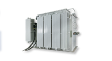
Heavy industrial environments demand robust cooling mechanisms. An oil immersed step up transformer is best for high-capacity applications. These units utilize mineral oil or synthetic fluids to absorb core heat. They offer superior cooling classifications, such as ONAN (Oil Natural Air Natural) or ONAF (Oil Natural Air Forced).
Liquid-filled units have different overload capacities compared to dry-types. They possess a longer thermal time constant. This means they can sustain temporary overloads much better before reaching critical temperatures. Their advanced insulation longevity makes them ideal for heavy grid infrastructure.
Placing equipment outside introduces distinct engineering challenges. Deploying an outdoor step up transformer requires careful thermal planning. You must size the unit for extreme ambient temperatures. Standard units are rated for a 30°C average ambient temperature.
Environments exceeding 40°C require capacity derating. High altitude installations also require derating. Air becomes thinner above 1,000 meters, severely reducing convective cooling efficiency. You must also evaluate NEMA 3R or IP54+ enclosure ratings. These ratings ensure protection against rain, sleet, and airborne dust particles. Footprint planning is essential to maintain proper clearance for ventilation.
Renewable energy generation requires specialized interconnection equipment. Solar and wind farms often utilize integrated systems. You might consider a ZGS step up transformer for these deployments. These pad-mounted units combine the transformer and protective switchgear into one secure enclosure.
Sizing these units requires unique considerations. You must integrate the specific step-up requirements of your solar inverters. Inverters have specific fault current limitations and harmonic profiles. The integrated switchgear must align perfectly with local grid interconnection standards. This ensures safe and compliant energy delivery to the utility grid.
You have completed your mathematical models. You have factored in your environmental constraints. Now, you must translate this raw data into a professional procurement document. Proper documentation prevents vendor misinterpretation.
Do not simply send vendors a requested kVA number. You must build a comprehensive Request for Quote (RFQ). A strong RFQ details several technical parameters. It clearly states the primary and secondary voltages. It includes the required vector group. It specifies the target impedance percentage (Z%). Impedance directly impacts voltage drop and short-circuit current calculations. Providing these details ensures vendors bid on identical engineering standards.
You must scrutinize potential manufacturers rigorously. Do not accept marketing claims at face value. Demand certified test reports for their previous builds. You should request documentation for Routine, Type, and Special tests. These tests must strictly follow IEEE C57.12.00 or equivalent IEC standards.
Furthermore, scrutinize stated efficiency ratings. In the United States, units must comply with DOE 2016 efficiency mandates. Verify these certifications before proceeding. A trustworthy vendor will provide these documents willingly.
You are now ready to engage engineering teams. Gather your preliminary load profile calculations. Collect your site environmental data. Compile your facility single-line diagrams. Submit these documents to vendor application engineers. They will use your data to finalize custom engineering quotes. This collaborative approach ensures your equipment meets exact operational demands.
Using a step up transformer sizing calculator is a complex engineering process. It is never a simple input-output math equation. You must evaluate multiple dynamic variables carefully. Always prioritize long-term electrical efficiency and site-specific ambient conditions. Accurate power factor modeling is non-negotiable. Avoid rushing to purchase a baseline, off-the-shelf unit based on incomplete math. Proper sizing prevents thermal degradation and nuisance tripping. We recommend submitting your detailed load profiles to certified application engineers. They will provide definitive specification validation and generate a custom, compliant RFQ for your facility.
A: Industry standard recommends adding 20% to 25% to your total calculated continuous load. This margin comfortably accommodates future facility expansion. It also prevents dangerous thermal stress during unexpected peak demand periods. However, you must always validate this specific margin against local NEC guidelines and your unique operational requirements.
A: Yes, altitude heavily impacts performance. Installations above 3,300 feet (1,000 meters) suffer from significantly reduced air density. Thinner air lowers convective cooling efficiency and decreases dielectric strength. You typically must derate the equipment capacity. Alternatively, you can order custom-engineered cooling solutions to offset the altitude penalty.
A: Buck-boost transformers are highly efficient for minor voltage corrections, like shifting 208V to 240V. However, they completely lack electrical isolation. For significant voltage step-ups or scenarios requiring strict fault isolation, they are unsafe. A standard, fully isolated step up transformer is mandatory in these critical applications.
A: A lower power factor directly increases the required kVA to deliver the same amount of real working power (kW). Reactive power takes up capacity in the system. Failing to divide your kW load by your actual facility PF will mathematically guarantee an undersized transformer. Always use accurate PF measurements.

