


Views: 0 Author: Site Editor Publish Time: 2026-09-20 Origin: Site


Accurate interpretation of a potential transformer wiring diagram is critical for safe and accurate voltage step-down in electrical systems. You cannot rely on guesswork when dealing with high voltages in an industrial grid. Misinterpreting schematics often leads to catastrophic equipment failure. It can easily cause severe phase-to-ground faults. In other scenarios, it produces inaccurate metering data, skewing your operational metrics. Such errors compromise your facility's safety and overall operational efficiency.
This guide provides a pragmatic, decision-oriented breakdown of standard wiring configurations. We outline critical grounding requirements. You will also discover the key specifications necessary to evaluate, select, and safely integrate these electrical units into your power infrastructure. Let us help you navigate these complex schematics confidently, ensuring your relays and meters receive precise, safe voltage signals.
Always verify polarity markings (H1/X1) on the diagram before physical installation to prevent phase-reversal and protection relay failures.
Single-phase and three-phase wiring configurations (such as Open-Delta or Wye-Wye) dictate the transformer’s suitability for metering versus protection applications.
Proper secondary grounding is a non-negotiable safety and compliance standard (IEEE/IEC) to prevent dangerous voltage build-up.
Evaluating a switchgear or medium voltage PT requires cross-referencing the wiring schematic with the physical insulation and clearance limits of your enclosure.
Reading a schematic requires understanding several universal symbols. Engineers use these symbols to convey electrical connections, voltage ratios, and safety mechanisms. You must interpret these diagrams systematically to avoid costly installation errors.
Wiring diagrams distinctly separate the high-voltage side from the low-voltage side. Identifying primary terminals is your first step. Manufacturers typically label primary terminals as H1 and H2. They label secondary terminals as X1 and X2. You will also find the step-down ratio explicitly stated on the schematic. For instance, a diagram might show a ratio of 14400:120V. This tells you the transformer reduces a 14.4kV primary voltage down to a safe 120V secondary voltage for metering.
Here is a quick checklist for verifying terminals:
Locate the high-voltage source connections (H1, H2).
Identify the low-voltage load connections (X1, X2).
Check the nameplate ratio against the schematic.
Verify terminal block numbering against the physical unit.
Polarity markings dictate the direction of current flow. The role of standard dot conventions is crucial in these diagrams. A dot next to H1 and a corresponding dot next to X1 indicates subtractive polarity. When current enters the H1 terminal, it simultaneously leaves the X1 terminal.
Implementation Risk: Reversing polarity during wiring introduces severe safety hazards. It compromises directional relays. If you wire the secondary backward, directional overcurrent relays will look in the wrong direction. They might fail to trip during a real fault. They could also trip unnecessarily during normal operations. Always test polarity before energizing the system.
A well-designed schematic always includes protective fuses. Identifying primary and secondary fuse placements within the diagram protects your investment. Primary fuses protect the larger electrical grid from a catastrophic transformer internal failure. Secondary fuses protect the transformer itself from short circuits occurring in the connected low-voltage meters.
Decision Lens: You must evaluate if the manufacturer's recommended fuse rating aligns with your load criteria. A fuse rated too high will not clear a secondary fault in time. A fuse rated too low will blow during normal transient surges. Cross-reference the secondary burden (measured in VA) with the fuse trip curve to ensure proper protection.
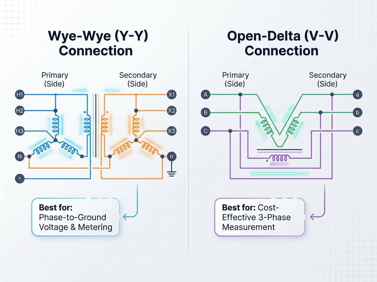
Your physical grid setup dictates your schematic configuration. You must match the transformer wiring to your specific measurement goals. Different connections yield different outcomes for metering and relay logic.
Assessing system requirements based on your specific grid setup is paramount. Single-phase systems simply require bridging H1 and H2 across the line and neutral. Three-phase systems are more complex. They require multiple transformers wired together to capture all phase relationships. You must decide between a few standard configurations.
The Wye-Wye configuration is highly common in industrial settings. It is best for standard three-phase systems requiring a neutral ground. You connect all H2 terminals to a common ground point. You do the same for all X2 terminals.
Outcomes: This setup provides highly accurate phase-to-ground voltage measurements. Relays use this data to detect ground faults quickly. However, this setup requires three separate transformers, demanding more physical space.
Sometimes you need three-phase data but lack space or budget. The Open-Delta connection uses only two transformers to monitor a three-phase system. It connects the transformers line-to-line rather than line-to-ground.
Outcomes: This is a highly cost-effective solution. However, it requires careful evaluation of capacity limits. You cannot measure phase-to-ground voltages accurately with an Open-Delta setup. It only provides phase-to-phase voltages. Ground fault detection becomes much harder under this configuration.
Comparison of Wiring Configurations
Configuration | Transformers Required | Primary Application | Measurement Type | Cost Efficiency |
|---|---|---|---|---|
Wye-Wye | 3 | Ground fault protection, accurate metering | Phase-to-Ground | Lower |
Open-Delta | 2 | Standard phase metering | Phase-to-Phase | Higher |
Delta-Wye | 3 | Specialized phase shifting | Mixed | Moderate |
Metering circuits need high accuracy at standard voltages. Protection circuits need reliability during extreme voltage spikes. You must configure a protection voltage transformer to ensure rapid fault detection.
If a fault occurs, voltages can spike massively. A metering core will deliberately saturate to prevent high voltages from reaching the delicate meter. A protection core must not saturate. It must faithfully reproduce the transient overvoltage so the relay knows exactly how bad the fault is. When reading the schematic, check the accuracy class. A class like "3P" or "6P" indicates a protection rating. Standard metering classes look like "0.2" or "0.5".
Safety is the foundational purpose of a correct wiring schematic. High-voltage systems pose immense risks. Proper grounding and isolation keep personnel safe during routine maintenance.
Look closely at the schematic. You will see the secondary winding explicitly tied to ground. This is usually at the X2 terminal or the star point in a Wye setup. Why do diagrams explicitly show this?
Implementation Reality: Transformers inherently feature capacitive coupling between the primary and secondary windings. Failing to ground the secondary allows this capacitance to pull the secondary voltage up to primary levels. Imagine 13.8kV sitting on a 120V terminal. This scenario will destroy the connected relays. It will severely endanger any personnel touching the low-voltage cabinet. Grounding bleeds off this dangerous capacitive charge.
Manufacturers do not design wiring schemes arbitrarily. Validating that the provided wiring diagram adheres to international standards ensures systemic reliability.
In North America, you must look for IEEE C57.13 compliance. Globally, you should verify IEC 61869-3 standards. These frameworks dictate allowable thermal burdens, accuracy classes, and insulation levels. If a schematic lacks references to these standards, you should question the equipment's pedigree.
High-noise electrical environments distort secondary voltage signals. Reading the diagram for electrostatic shields between primary and secondary windings is essential. The schematic often depicts a dashed line between the winding coils, tied to a ground symbol. This shield intercepts high-frequency transients. It prevents electromagnetic interference from reaching sensitive digital meters.
Voltages above 5kV introduce new physical constraints. The wiring diagram alone does not tell the whole story. You must map the schematic to real-world physics.
Diagrams for a medium voltage potential transformer (typically 5kV to 35kV) differ significantly from low-voltage counterparts. Low-voltage schematics often ignore spacing requirements. Medium voltage schematics usually include specific fuse sizes, phase barriers, and clearance notes. The electrical stress on the core requires massive epoxy casting, which changes how you route the primary cables.
You must translate diagrammatic dimensions into physical installation reality. A schematic might show a simple line connecting to H1. In reality, that line represents a thick, high-voltage busbar.
Evaluating Basic Impulse Level (BIL) ratings alongside the schematic is critical. A 15kV system might require a 95kV BIL rating. This means the insulation can withstand a 95kV lightning strike for a few microseconds. The physical clearance between the H1 terminal and the grounded enclosure must support this BIL. If you install the unit too close to a metal wall, an arc flash will occur regardless of how perfectly you followed the schematic.
You face two main connection strategies: line-to-line versus line-to-ground. You must choose the right configuration based on system grounding.
Solidly Grounded Grids: Use line-to-ground connections. The system neutral handles fault currents safely.
Ungrounded Grids: Ungrounded systems experience massive voltage shifts during a phase-to-ground fault. The healthy phases jump to line-to-line voltage levels. You must select units rated for line-to-line voltage across the line-to-ground terminals to prevent insulation failure.
Integrating these devices into metal-enclosed cabinets requires mechanical planning. You must align the electrical schematic with mechanical operation.
Evaluating the mechanical and electrical disconnects shown in a switchgear potential transformer diagram prevents maintenance nightmares. Fixed transformers bolt directly to the busbar. You must de-energize the entire switchgear line up to replace a fuse.
Draw-out schematics feature specialized symbols indicating sliding contacts. These allow operators to safely rack out the transformer assembly while the main bus remains energized. The diagram will show primary finger clusters and secondary disconnect plugs. Ensure you understand how these mechanical breaks integrate into your safety interlocking procedures.
Modern switchgear relies on digital communication. You must map the secondary terminals directly to digital meters or protective relays inside the panel. Older schematics assumed electromechanical relays, which drew heavy current (high burden). Modern digital relays draw almost no current. You must verify the transformer's VA rating matches the modern, low-burden digital devices. Oversizing the VA rating can sometimes reduce accuracy at lower loads.
Never install a unit simply because the box arrived. Follow strict verification protocols.
Verification: Match the physical nameplate data to the approved schematic. Check ratios, thermal limits, and accuracy classes.
Testing: Conduct a ratio test to ensure the windings are intact.
Polarity Verification: Use a polarity tester to confirm the H1/X1 dot relationship is accurate.
Insulation Resistance: Perform a Megger test before energizing the circuit to verify the epoxy casting survived shipping.
Correctly reading a potential transformer wiring diagram is the first step in ensuring accurate procurement, safe installation, and reliable system protection. It requires a firm grasp of terminal labeling, polarity conventions, and grounding imperatives. Misunderstanding a schematic compromises personnel safety and equipment lifespan.
Do not rely on assumptions. Always cross-reference the manufacturer’s schematic with your facility’s specific protection and metering needs. Verify physical clearances, BIL ratings, and secondary fuse sizing before applying power.
Your next action should be to consult with a certified electrical engineer or your equipment manufacturer. Validate your chosen configuration and request standard-compliant schematics for your specific application. A proactive review today prevents catastrophic downtime tomorrow.
A: Incorrect polarity can cause meters to read backward and protective relays to fail during a fault, leading to severe equipment damage. Directional overcurrent relays rely on precise polarity to determine where a fault is located. Reversing it blinds your protection system.
A: Generally, no. Protection voltage transformers are designed to maintain accuracy during high-voltage fault conditions by avoiding core saturation. Metering transformers are optimized for high accuracy at normal operating voltages. They saturate quickly to protect sensitive meters during a surge.
A: Primary fuses protect the broader power system from an internal transformer failure. They clear the device from the grid. Secondary fuses protect the transformer itself from short circuits occurring in the connected low-voltage wiring, meters, or relays.
A: Line-to-line measures the voltage between two distinct phases. Line-to-ground measures the voltage between one phase and the system ground. The choice depends on your specific relay setup, the desired metering data, and whether your system is solidly grounded or ungrounded.

