


Views: 0 Author: Site Editor Publish Time: 2026-09-05 Origin: Site


Selecting the correct transformer size carries extremely high stakes for commercial and industrial facilities. You simply cannot afford to guess your load calculations. Oversizing creates unnecessary capital expenditure and forces you to absorb high core losses continuously. Conversely, undersizing invites catastrophic failure, dangerous overheating, and crippling operational downtime. We must view the sizing process as a critical procurement decision rather than a simple mathematical exercise. You must carefully balance your raw load requirements against physical environmental constraints. You also have to navigate mandatory compliance rules, especially strict NEC standards. Securing the proper unit protects your expensive downstream equipment and ensures facility safety. This guide provides a definitive, step-by-step framework to navigate this process smoothly. You will learn how to accurately calculate your base kVA and apply essential safety margins. We will also help you select the exact enclosure needed for your specific operational environments.
The foundational formula for a 3 phase transformer requires calculating Volts × Amps × 1.732 (the square root of 3), then dividing by 1,000 to find the base kVA.
Industry standard practice dictates adding a 20% to 25% safety margin to accommodate peak loads, inrush currents, and future facility expansion.
Calculated kVA must be rounded up to the next commercially available standard transformer size (e.g., 15, 30, 45, 75, 112.5 kVA).
Environmental placement directly dictates the enclosure type; an indoor three phase transformer requires different ventilation and NEMA ratings compared to an outdoor three phase transformer.
Accurate raw calculation forms the absolute baseline for preventing costly procurement errors. You must establish the core electrical variables before purchasing any equipment. If you skip this data collection phase, your entire sizing effort will fail. We need to define exactly what your facility requires before exploring catalogues.
Before touching a calculator, you must gather three specific numbers. You can usually find these figures on your equipment nameplates or electrical drawings.
Load Voltage (Secondary Voltage): This represents the voltage your equipment actually needs to operate. Common secondary voltages include 208V or 480V.
Supply Voltage (Primary Voltage): This is the voltage coming from your utility provider or main facility distribution board. Common primary voltages include 480V or 4160V.
Line Current: This indicates the total amperage required by your connected load at full operation. You must calculate the total draw if powering multiple devices.
The calculation framework relies on one universal equation. The formula is: kVA = (Volts × Amps × 1.732) / 1000. You might wonder why we multiply by 1.732. This specific number represents the square root of 3 ($\sqrt{3}$). Three-phase power systems transmit three alternating currents simultaneously. These currents phase exactly 120 degrees apart from one another. Multiplying by 1.732 correctly accounts for this geometric phase separation. It converts simple linear measurements into true apparent power across all three legs.
Let us walk through a practical calculation scenario. Imagine you have a 480V industrial motor. This motor requires a continuous 60 Amps to operate under normal conditions.
First, multiply the Volts and Amps: 480 × 60 = 28,800.
Next, multiply by the phase factor: 28,800 × 1.732 = 49,881.6.
Finally, divide by 1,000 to find your kVA.
The final result is roughly 49.9 kVA. This represents your absolute minimum raw power requirement.
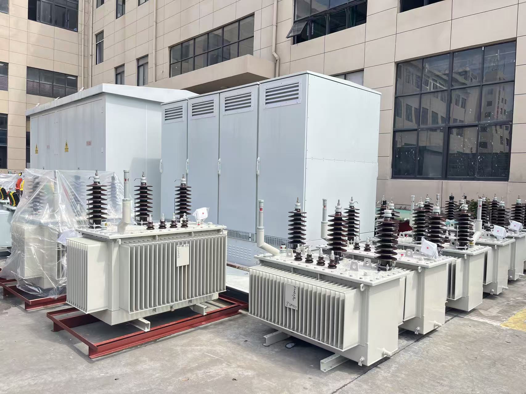
Buyers cannot purchase custom kVA sizes easily. Manufacturers take months to build custom units. Instead, you must map your raw calculations to commercial availability. This decision-stage logic ensures faster procurement and better overall system reliability.
Industry standard practice requires adding a safety margin to your raw kVA. Experts strongly recommend applying a 20% to 25% buffer. You should never run a transformer at maximum capacity continuously. Operating near 100% load leads to rapid thermal degradation of the insulation. Heat destroys electrical equipment quickly.
Furthermore, you must account for motor startup demands. Motors draw massive inrush currents when they first spin up. These temporary surges easily exceed normal rated running loads. If you size exactly to your running load, startup surges will trip breakers or cause severe voltage drops. A 25% buffer prevents these nuisance issues entirely.
Let us return to our previous example. We calculated a raw need of 49.9 kVA. Adding a 25% safety margin yields 62.4 kVA. However, 62.4 kVA is not a standard manufactured size. You must look at a standard sizing chart.
Capacity Range | Standard Industrial Sizes (kVA) |
|---|---|
Small Commercial | 15, 30, 45 |
Medium Commercial | 75, 112.5, 150 |
Large Industrial | 225, 300, 500, 750 |
Heavy Industrial | 1000, 1500, 2000, 2500 |
Your actionable advice is clear here. Your required 62.4 kVA falls between the standard 45 kVA and 75 kVA sizes. You must always round up to the next available size. Therefore, you should select the 75 kVA standard size. Rounding down to 45 kVA guarantees overheating and eventual failure.
Engineers frequently face a highly specific field problem. They often need to use a three-phase source to power single-phase loads. This technical nuance requires careful planning. If you manage mixed loads, your sizing calculations become significantly more complex.
Phase balancing serves as your most critical priority here. You cannot put your entire single-phase load on just one leg of the unit. Connecting everything to Phase A will overload that specific coil. You must distribute single-phase loads evenly across all three phases. Good engineering ensures balanced current draw from the utility. Balanced loads keep core temperatures stable and extend equipment lifespans.
Severe phase imbalances create massive operational risks. If one coil carries significantly more load than the others, it will overheat quickly. The overall unit might look lightly loaded on paper. However, one specific phase might be actively burning up. To prevent this, you might need to size up the entire unit. Applying a heavy de-rating factor protects the heavily loaded coil from thermal failure.
Secondary configurations play a huge role in single-phase distribution. We must look at Wye versus Delta connections. You generally require a Wye secondary configuration to serve standard 120V or 277V single-phase loads. Wye configurations provide a dedicated neutral wire. This neutral point acts as the necessary return path for single-phase currents. Delta configurations lack this central neutral connection. Therefore, standard Delta setups remain largely unsuitable for typical single-phase office distribution.
The physical installation location entirely dictates the lifespan of your unit. Different environments require vastly different solution categories. You must match the enclosure type to the physical realities of your specific site.
Specifying an indoor three phase transformer involves distinct spatial challenges. Facility managers usually face strict footprint limitations. Electrical rooms rarely offer extra clearance. You must also calculate structural floor-loading weight restrictions. These units are incredibly heavy. Always verify your concrete slab limits before installation.
Furthermore, indoor units demand strict ventilation clearance. They rely purely on ambient air circulation to reject core heat. You typically need at least six inches of wall clearance. We highly recommend NEMA 1 or NEMA 2 enclosures for indoor spaces. They effectively block falling dirt and light liquid drips. Dry-Type models remain the absolute standard for indoor use. They eliminate the severe fire risks and spill hazards associated with liquid-filled models.
Specifying an outdoor three phase transformer requires a completely different mindset. Weather resistance becomes your primary engineering concern. You must account for ambient temperature extremes, heavy rain, and general site security. We strongly recommend specifying NEMA 3R rainproof enclosures for standard outdoor locations. If you operate near corrosive environments like oceans or chemical plants, you need NEMA 4X stainless steel enclosures.
Outdoor applications typically utilize heavy concrete pad-mount installations. For large-scale industrial three phase transformer applications, you will likely need oil-filled units. Oil provides vastly superior cooling capabilities for massive continuous loads. Just ensure you build proper secondary containment structures to capture any potential fluid leaks.
Procurement often goes wrong during the final specification stages. Understanding these implementation realities protects your facility investment. Let us examine the most common mistakes engineers and buyers make.
Ignoring non-linear loads ranks as a top failure point. Modern facilities rely heavily on VFDs (Variable Frequency Drives). IT equipment and LED lighting networks also dominate modern electrical loads. These digital devices alter the standard electrical sine wave. They create severe harmonic distortion. Harmonics generate extreme internal heat within the coils. Standard units will overheat and fail quickly under heavy harmonics. To prevent this, you must specify a K-rated transformer. K-ratings designate the unit's ability to handle harmonic heat safely.
We must strongly emphasize NEC compliance risks. Your chosen transformer size directly dictates your primary and secondary overcurrent protection. It also dictates your electrical conductor sizing. Breaker sizing must align perfectly with National Electrical Code (NEC) Article 450. If you upsize the unit for future expansion, you must also upsize the supply breakers and wires accordingly. Failing to match these elements creates severe code violations and terrible fire hazards.
Finally, buyers often fail to account for altitude and temperature extremes. Air density drops significantly at higher elevations. Thinner air absorbs less heat from the enclosure. Installations above 3,300 feet (1,000 meters) require specific de-rating calculations. The same logic applies to extreme ambient heat. If your electrical room consistently exceeds normal temperatures, you cannot rely on the standard nameplate capacity. You must de-rate the capacity to prevent catastrophic thermal failure.
Sizing correctly requires disciplined adherence to established electrical rules. You must rely on the strict formula of Volts times Amps times 1.732. After finding your base number, always apply the mandatory 25% safety margin. Finally, carefully map that resulting number to the nearest standard commercial size. Never cut corners on these foundational steps.
Your next steps should focus on verification. Audit your complete facility load list immediately. Determine your exact NEMA enclosure needs based on the planned installation location. Before you generate any final purchase order, consult with a licensed electrical engineer. Have a trusted technical sales representative verify your final specification. This rigorous dual-check approach ensures lasting operational reliability.
A: You use the standard three-phase power formula. Multiply your Load Voltage by your Line Amperage. Then, multiply that result by 1.732 (the square root of 3). Finally, divide the total by 1,000. The equation looks like this: (V × A × 1.732) / 1000 = kVA.
A: Generally, no. You cannot feed single-phase power into a standard three-phase unit without specialized phase-converter equipment. The magnetic core requires three alternating currents to function properly. However, a 3 phase transformer can easily supply power to single-phase downstream loads if wired correctly.
A: Oversizing brings distinct commercial downsides. You will face a much higher upfront capital cost. The unit will also demand a larger physical footprint. Additionally, you will suffer from higher idle core losses continuously. While the unit will run much cooler, the wasted energy costs add up over time.
A: kVA represents "apparent power," which is the total power moving through the system. kW represents "actual power," which is the true working power consumed by your loads. The difference between these two values is dictated by your system's Power Factor. Transformers are always sized in kVA.

