


Views: 0 Author: Site Editor Publish Time: 2026-08-26 Origin: Site


Electromagnetic induction powers our modern world. However, translating this physical principle into industrial-scale power requires specialized engineering. The specific design of your facility equipment dictates system uptime, peak load capacity, and long-term energy costs. Misunderstanding how internal winding configurations and cooling mechanisms interact often leads to costly infrastructure mistakes. You might accidentally over-specify equipment, suffer from poor thermal management, or fail strict regional efficiency standards.
We move beyond basic textbook theory here. You will learn how three-phase mechanics directly influence industrial procurement criteria, energy loss evaluation, and operational efficiency. We provide actionable steps to align your power infrastructure with actual operational loads. By examining core materials and advanced cooling methods, you can make informed decisions for your next facility upgrade.
A 3 phase transformer utilizes three sets of primary and secondary windings on a single shared core, offering significant footprint and material efficiency advantages over three single-phase units.
Winding configurations (Delta vs. Wye/Star) dictate voltage outputs, harmonic mitigation, and grounding capabilities for specific industrial loads.
Cooling methodology—specifically in a three phase oil immersed transformer—is critical for managing operational heat and extending asset lifespan.
Procurement should be strictly tied to core efficiency standards, carefully weighing upfront capital expenditure against long-term no-load losses (e.g., evaluating an S13-M three phase transformer vs. a highly efficient S20-M three phase transformer).
Industrial power systems rely heavily on continuous and balanced energy transfer. To achieve this, engineers utilize a specific alternating current (AC) framework. Three separate AC circuits operate simultaneously. They do not peak at the same time. Instead, they operate with a strict 120-degree electrical phase shift.
This 120-degree separation allows continuous power delivery. When one phase drops in voltage, the other two phases compensate. This prevents the pulsating power output typical of single-phase systems. Heavy industrial loads, such as large induction motors, require this smooth, uninterrupted power delivery. It prevents mechanical vibration and ensures consistent torque.
You might wonder how this electrical phasing impacts the physical equipment. The secret lies in the shared magnetic core. A standard design utilizes three limbs on a single metal frame. Because the electrical currents are 120 degrees apart, their corresponding magnetic fluxes also shift by 120 degrees.
Phase A generates its magnetic flux.
Phases B and C generate their fluxes slightly later.
These three magnetic fields meet in the common core sections.
Due to vector mathematics, the sum of these three fluxes equals zero at the center point.
This natural cancellation is a massive engineering advantage. It eliminates the need for a massive central return path for the magnetic field. You save a tremendous amount of core steel compared to using three separate single-phase units.
Shared-core efficiency directly reduces the physical footprint of the unit. It drastically lowers the overall weight. Substation design becomes much simpler when accommodating a single, compact unit. Logistics, rigging, and installation costs drop significantly. You also reduce the required volume of dielectric fluids needed for insulation.
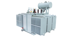
Internal copper or aluminum coils determine how a facility uses incoming power. Engineers arrange these primary and secondary coils in specific geometric patterns. The two most prominent patterns are Delta and Wye. Choosing the right configuration dictates your facility's grounding capabilities and harmonic mitigation.
Delta Connections:
The Delta configuration connects the ends of three windings in a closed loop. It resembles a triangle. Engineers use Delta primarily for industrial motor loads and long-distance power transmission. It offers exceptional reliability. If one phase winding fails, the unit can often continue operating in an "open-delta" configuration. It delivers reduced capacity but prevents a total facility shutdown. Delta systems trap certain harmonic currents, keeping them out of your main distribution grid.
Wye (Star) Connections:
The Wye configuration connects one end of each winding to a common central point. This creates a star shape. This central point provides a dedicated neutral connection. It is absolutely essential for distributing power to mixed commercial or industrial loads. Wye allows you to draw both phase-to-phase voltages (for heavy equipment) and phase-to-neutral voltages (for standard lighting and office electronics) from the same unit. Grounding the neutral point also stabilizes the system during electrical faults.
Combining Delta and Wye across the primary and secondary sides creates a specific vector group. You often see designations like Dyn11 on an equipment nameplate.
D: Represents a Delta primary.
y: Represents a Wye secondary.
n: Indicates a neutral point is brought out.
11: Denotes a 30-degree phase shift between primary and secondary voltages, referencing a clock face.
Matching vector groups is a hard requirement for synchronizing parallel units. If you attempt to connect two units with different phase shifts, catastrophic circulating currents will destroy the equipment.
Electrical resistance inside the coils generates intense heat. The magnetic core also produces heat due to eddy currents. Managing this thermal output is non-negotiable. A three phase oil immersed transformer utilizes specialized fluids to survive these extreme conditions.
Dielectric oil serves two critical roles. First, it provides high-grade electrical insulation between tightly packed internal components. It prevents electrical arcing between the high-voltage coils. Second, it acts as a highly efficient thermal conduit. The fluid absorbs heat from the active internal parts and carries it away.
Systems typically rely on Oil Natural Air Natural (ONAN) cooling mechanics. This process uses passive convection currents. As the oil absorbs heat from the core, its density decreases. The hot oil naturally rises to the top of the tank. It flows into external radiators or cooling fins. Ambient air passes over these fins, absorbing the heat. The oil cools, becomes denser, and cycles back down to the bottom of the tank.
For heavier loads, engineers implement Oil Natural Air Forced (ONAF) systems. This adds automated external fans to blow air across the radiators, accelerating the heat dissipation process.
Cooling Mechanism Comparison Chart
Cooling Designation | Oil Movement | Air Movement | Typical Application |
|---|---|---|---|
ONAN | Natural Convection | Natural Convection | Standard base-load distribution, minimal maintenance. |
ONAF | Natural Convection | Forced (Fans) | High-demand facilities, variable peak loads. |
OFAF | Forced (Pumps) | Forced (Fans) | Ultra-high capacity substations. |
Oil-immersed systems require ongoing monitoring. Facility managers must conduct regular visual inspections for leaks. More importantly, you must perform Dissolved Gas Analysis (DGA).
DGA acts as a blood test for your equipment. As internal insulation degrades or minor arcing occurs, specific gases dissolve into the oil. High hydrogen levels indicate corona discharge. Elevated acetylene warns of severe internal arcing. Routine DGA detects these incipient faults long before they cause a catastrophic failure. Additionally, environmental regulations mandate secondary spill containment infrastructure around the pad to prevent soil contamination during leaks.
Procurement teams must carefully evaluate energy efficiency ratings. Upfront capital costs only represent a fraction of the lifetime expense. Energy losses dictate your actual operational budget over a 30-year lifespan.
We classify energy waste into two distinct categories.
Core losses, or "no-load" losses, occur continuously. As long as the unit remains energized, it consumes power. The alternating magnetic field creates hysteresis and eddy currents within the steel core. This generates heat and wastes electricity 24 hours a day, regardless of your facility's activity.
Copper losses, or "load" losses, tie directly to electrical resistance in the windings. These losses fluctuate based on your actual power consumption. As your facility draws more current, copper losses increase exponentially.
The S13-M three phase transformer represents a widely adopted, highly reliable industrial standard. It utilizes high-quality, grain-oriented silicon steel cores.
Decision Lens: This tier offers a highly balanced ratio of capital expenditure to operational expenditure. It perfectly suits facilities with standard, fluctuating load cycles. If your plant shuts down operations at night, or experiences highly variable seasonal demands, this model provides rugged reliability without an exorbitant upfront premium.
The next generation of efficiency relies on advanced metallurgical science. An S20-M three phase transformer utilizes highly refined silicon steel or cutting-edge amorphous alloys. These materials drastically reduce magnetic resistance.
Decision Lens: This equipment carries a higher initial procurement cost. However, it drastically slashes no-load losses. It proves structurally necessary for facilities operating under strict ESG (Environmental, Social, and Governance) mandates. If your facility runs continuous 24/7 baseloads—like data centers or continuous-process chemical plants—the financial return is rapidly accelerated through massive reductions in daily energy waste.
Buying heavy electrical infrastructure requires precise attention to detail. A poorly specified unit leads to chronic overheating, wasted capital, or dangerous compliance failures.
Calculating your true KVA (Kilovolt-Ampere) requirement is crucial. Many engineers fall into the trap of unnecessary oversizing. They stack "safety factors" on top of inflated load estimates. An oversized unit operates inefficiently. It incurs higher no-load losses and demands a larger, more expensive footprint. You should conduct a thorough load profile analysis. Determine your actual continuous demand, peak starting currents for large motors, and realistic future expansion plans before finalizing the KVA rating for your 3 phase transformer.
Never accept delivery without verifying Factory Acceptance Testing (FAT) reports. You must demand documentation for routine dielectric tests. These include applied voltage and induced voltage tests to confirm insulation integrity. You must also review temperature rise tests. These prove the cooling system handles the rated load without exceeding safe thermal limits. Finally, verify the manufacturer's certified loss measurements. Ensure the actual no-load and load losses match the contractual specifications.
Evaluate your site constraints well before delivery. Oil-immersed units require specific environmental considerations. You must verify local fire clearance regulations. Determine if you need blast walls or fire-suppression systems. Assess your concrete foundation. It must support the extreme weight of the fully assembled unit, including thousands of gallons of oil. Finally, ensure adequate outdoor ventilation. Obstructions near the radiators will severely degrade ONAN cooling efficiency.
Understanding the internal workings of this equipment gives you a distinct engineering advantage. It is ultimately about managing the delicate interplay between magnetic efficiency, thermal dissipation, and specific load demands. Your choices regarding core materials, winding vector groups, and cooling fluids directly shape facility reliability.
Your next step requires active data gathering. We encourage buyers to conduct a rigorous, week-long load profile analysis on their current infrastructure. Take these real-world numbers and request standardized energy loss calculations from trusted manufacturers. Compare the lifecycle energy consumption of legacy models against the advanced S13-M or S20-M efficiency tiers. Armed with this hard data, you can specify equipment that guarantees uninterrupted power while minimizing long-term financial waste.
A: It provides reduced cost, lighter weight, a smaller physical footprint, and higher overall efficiency. This stems from utilizing a shared magnetic core. However, a major failure requires replacing the entire unit rather than swapping out a single phase bank.
A: Annual visual inspections and basic oil sampling represent the standard baseline. We recommend comprehensive Dissolved Gas Analysis (DGA) every 1–3 years. The exact frequency depends heavily on your facility's load stress and ambient operating environment.
A: The primary difference lies in the core material and design geometry. The S20-M series features significantly lower no-load (core) losses. This makes it substantially more energy-efficient over its lifespan, despite requiring a higher upfront purchase price compared to the standard S13-M series.

